

Three-Way Valve Mixing vs Diverting: A Process Automation Engineer’s Guide
The engineer who commissioned the project entered the mechanical room and immediately detected the sound. A sharp, rhythmic chatter echoed through the space which produced a sound that bounced off the concrete walls. The air handling unit’s new 3-way valve operated continuously as it struck its seat. The plug developed scoring within three weeks while the actuator functioned at excessive temperatures and the building experienced supply air temperature variations of 4 degrees Celsius. The root cause? The contractor had installed a mixing body in a diverting configuration. The owner lost $3,200 because of this single mistake which included both parts and labor expenses during three months of inadequate comfort management.
The three-way valve mixing versus diverting distinction represents an essential detail for your work on three-way valves which you will specify and install and test. The two functions look similar on a drawing, but they rely on different internal seat geometry, flow direction, and pressure-drop behaviour. Proper selection results in continuous control operations together with extended equipment durability. The exact result that occurred in the previous example will happen when you make a selection which leads to an incorrect outcome.
In this guide, you’ll learn how three-way valve mixing vs diverting designs work at the engineering level, when to specify each 3-way control valve type, and how to integrate them into modern building automation systems. The study will examine hydronic system requirements which most specifiers do not understand.
Want to see Black Ant’s three-way valve range before you read on? Explore our electric three-way valves →
Three-Way Valve Mixing vs Diverting: The Fundamental Difference

Mixing Valves (Converging Flow)
A three-way mixing valve has two inlet ports which engineers usually designate as A and B while it operates through a single common outlet port which they name AB. The system functions to mix two incoming fluid streams into one complete output stream. The valve body contains a single plug which controls the opening size through both entry points to determine the flow distribution from port A and port B.
HVAC systems depend on mixing valves to function as their primary temperature control components. They mix hot water with cold water to achieve an exact supply temperature. They also function in underfloor heating systems domestic hot water recirculation systems and industrial processes which require precise ratio blending of two chemical reactants.
Engineering requires two inlet streams to maintain matching pressures because this condition enables stable mixing operations. A stream at higher pressure will dominate the mixing process when one inlet operates at much greater pressure than another. The lower pressure stream causes poor mixing results together with the potential of flow reversing through the lower pressure section.
Diverting Valves (Diverging Flow)
The comparison between the diverting valve and the mixing valve shows different geometry results. The three-way diverting valve operates through its single inlet port (AB) which connects to both outlet ports (A and B). The system needs to redirect its incoming stream because it must send the stream to one of its two pathways.
Diverting valves are common in coil bypass applications. The system operates through a valve which sends some fluid through the bypass leg while the rest goes to the coil. They also serve equipment switching duties, for example, routing flow to a standby heat exchanger when the primary unit is taken offline for maintenance.
Here’s the point that trips up even experienced installers: mixing and diverting bodies are not interchangeable. A characterised globe valve designed for mixing service has seat geometry and flow direction optimised for converging flow. If you reverse-pipe it as a diverting valve, the plug can slam against the seat at partial stroke positions. That chattering sound is the telltale sign of rapid seat damage and imminent failure. As the Belimo project planning notes make clear, some 3-way characterised control valves must never be used in the reverse direction.
Why Port Labelling Matters on Site
The actual process of assigning port designations becomes complex because people make errors which persist despite the straightforward nature of this task. Always verify:
- Mixing valve: A + B → AB (two inlets, one outlet)
- Diverting valve: AB → A + B (one inlet, two outlets)
The valve body contains a flow arrow which needs to match the service direction that has been designated. If the installation process overlooks the arrow, then even a top-quality valve will experience early failure.
Valve Design Types: Globe, Ball, and Plug
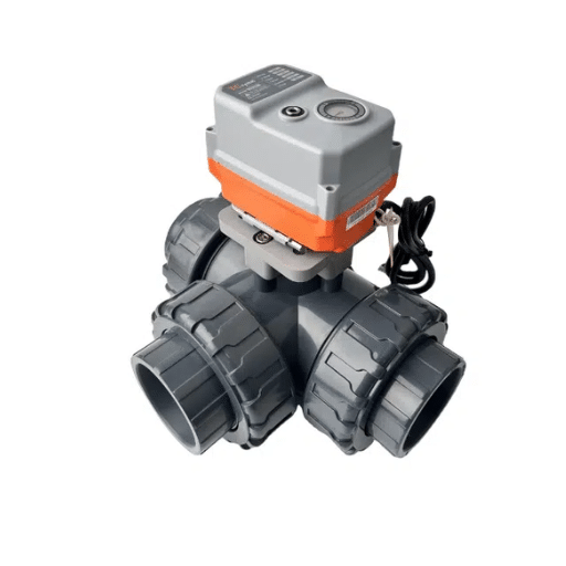
Not every 3-way control valve is built the same. The right design depends on whether you need precise modulating control or fast on-off switching. The choice between globe, ball, and plug designs is closely related to the broader linear vs rotary electric control valves decision — globe valves are linear, while ball and plug valves are rotary.
Three-Way Globe Control Valves
Globe-style three-way valves are the go-to choice for precise modulating control. A linear stem moves a plug perpendicular to the seat, which results in high-precision flow control through the throttling mechanism. The system provides specific flow rate characterizations which include equal percentage and linear flow curves that match well with proportional temperature control systems.
The most accurate globe valves provide optimal performance for process automation and HVAC system control. A properly specified modulating globe valve can hold positioning accuracy within ±1% of stroke. The temperature control system needs that level of precision to manage cleanroom air supply temperatures and to maintain chemical reactor jacket temperature setpoints.
Black Ant’s electric globe control valve range includes modulating actuators with 4–20mA and 0–10V inputs, plus optional RS485/Modbus RTU communication for direct BMS integration. The DN15–DN100 sizing covers the majority of HVAC and light process applications.
Three-Way Ball Valves: L-Port vs T-Port
Ball valves use a hollow sphere with machined ports to direct flow. They actuate in a quarter-turn (90°) motion, making them faster than globe valves but less precise for throttling service.
|
Configuration |
Bore Shape |
Best For |
Shut-off Capability |
|---|---|---|---|
|
L-Port |
L-shaped |
Diverting / switching |
Can isolate one side port |
|
T-Port |
T-shaped |
Mixing, splitting, or diverting |
Cannot fully shut off all three ports |
The L-port ball valves establish a connection between the central port and one of the two side ports. The system works best with on-off diverting applications which direct flow towards either tank A or tank B.
T-port ball valves offer more flexibility. The system can connect its center port to either side or both sides at the same time or it can establish a straight-through connection. This makes them suitable for mixing, splitting, or simple diverting. The three ports become unusable when the system requires complete shut-off. The system maintains at least one flow path active through all operational states.
Black Ant’s electric ball valve line includes DN15–DN100 three-way models in brass and stainless steel, with AC220V and DC24V actuator options. The 2–5 second actuation time suits emergency isolation and automated switching sequences.
Three-Way Plug Valves
Plug valves use a tapered or cylindrical plug with a machined port to direct flow. The system operates through basic design yet handles contaminated and thick fluids because of its strong construction. Process automation systems use them in chemical plants and mining operations and marine services that handle slurries or particulates which would harm the delicate components of a globe valve.
Plug valves operate as on-off control devices. The design provides modulating features but cannot achieve the same throttling accuracy which a characterised globe valve delivers.
How to Choose the Right 3-Way Control Valve for Mixing or Diverting Service
Valve Authority and Pressure Drop
The singlemost important element which people tend to forget about three-way valve selection process exists through valve authority control. The authority of the valve determines whether the valve will operate at a constant flow rate or will make uncontrolled movements from its designated flow rate.
Authority (N) is defined as:
N = ΔP_valve / ΔP_branch
The branch pressure drop occurs because the valve and its connected coil or heat exchanger system experience a complete pressure decline.
- The valve should take a high pressure drop which equals or exceeds the coil pressure drop for mixing applications. The target authority needs to exceed 40% with the preferred target set at 50%. This configuration ensures that the valve flow patterns control the entire branch system which enables the controller to maintain steady operation.
- The valve needs to handle a low pressure drop which should reach approximately 20% of the total branch pressure drop while maintaining a value below the coil pressure drop limit. The practice of oversizing pressure drop requirements in diverting operations leads to inefficient flow patterns which result in pump systems reaching their maximum capacity.
Marcus selected an economical three-way mixing valve with 15% authority for the university lab’s chilled water system because he wanted to reduce installation expenses. The controller spent all day hunting. The supply air temperature displayed a 3°C range which led the lab manager to threaten payment withholding. The loop reached stability within minutes after upgrading to a valve which operated at 55% authority. The total cost of the upgrade reached $180. All complaints about comfort in the space disappeared when we made this change.
Modulating vs On-Off Control Requirements
Globe valves serve as the suitable option for controlling temperature and flow and pressure modulations. Ball valves serve as the superior choice for performing on-off operations and creating emergency shutdowns and directing equipment between different paths. The application of a ball valve for ongoing throttling results in seat damage and ineffective control and reduced operational lifespan. Industry data shows that on-off valves which operate in throttling service experience failures at a rate which is five to ten times higher than that of correctly selected modulating valves.
Material and Connection Selection
- Bronze or cast iron: Standard for HVAC hot and chilled water
- 304/316 stainless steel: Required for corrosive fluids, pharmaceutical processes, or food-grade applications
- Flanged connections: Preferred for maintenance access in commercial and industrial systems
- Threaded connections: Common for smaller sizes (DN15–DN50) in residential and light commercial work
One practical note: if your system uses glycol at concentrations above 30% upsize the valve by one Kvs or Cv step The increased viscosity and reduced heat transfer capacity of glycol mean a nominally sized water valve will underperform.
Actuator and Control Signal Integration
Modern process automation demands more than a mechanical valve. The actuator and control interface are just as important as the body design.
|
Signal Type |
Typical Use |
Black Ant Compatibility |
|---|---|---|
|
4–20mA analog |
Modulating control from DDC/PLC |
Standard on globe and ball valve actuators |
|
0–10V |
BMS analog outputs |
Standard on modulating actuators |
|
RS485/Modbus RTU |
Digital BMS integration |
Available on fan coil control valves and globe valves |
|
BACnet MS/TP |
Building automation networks |
Available on select HVAC control valves |
For BEMS integration, specify valves with feedback signals where possible. A position feedback signal lets the building management system confirm that the valve has actually moved to the commanded position, a critical diagnostic capability for commissioning and fault detection. Our building automation 101 guide explains how to wire Modbus and BACnet devices into tiered BAS architectures.
Application-Specific Recommendations
HVAC and Building Automation
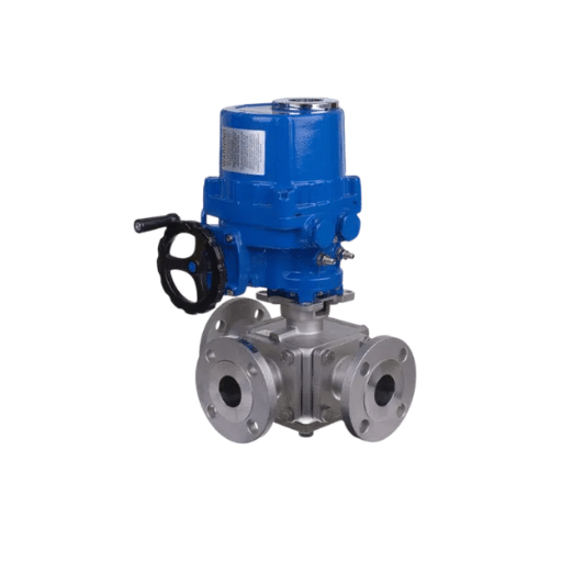
All constant-flow HVAC systems use three-way valves as their main control element. The application of these valves can be found in the following locations:
- Fan coil units: A fan coil 3-way valve maintains constant flow through the primary loop while modulating flow through the coil. This system applies traditional constant-flow operation which uses fixed-speed pumps for its functionality.
- Air handling units: Mixing valves on coil returns control supply air temperature. Some designs use diverting valves on the supply side to bypass the coil.
- District heating substations: Three-way mixing valves blend primary supply and return water to maintain the secondary loop setpoint. This system protects downstream equipment from high temperature conditions which could lead to damage.
- Underfloor heating: Mixing valves combine boiler supply water with cooler return water to achieve the low supply temperatures (typically 35–45°C) required by floor circuits.
Black Ant’s fan coil control valve range includes DN15, DN20, and DN25 three-way configurations with 2–5 second actuator response and ±0.5°C zone control accuracy when paired with our room temperature controllers. The RS485, BACnet, and Modbus protocol support enables plug-and-play integration with Honeywell, Siemens, Johnson Controls, and Schneider BMS platforms.
Industrial Process Control
- Chemical processing: T-port stainless steel ball valves control the flow of reactants which connect two batch reactors. Globe valves execute exact proportions of two different substances.
- Food and pharmaceutical: Three-way diverting valves direct process fluids through Clean-in-Place (CIP) skids without disassembly.
- Power generation: Diverting valves send steam and condensate to different heat exchangers which operate during maintenance periods.
- Water treatment: T-port ball valves control the operation of filter banks by switching between service and backwash modes.
When Sarah’s team at a pharmaceutical plant in Ireland needed to upgrade their CIP routing valves they evaluated several European brands. The lead times required 14 to 16 weeks for delivery. They switched to Black Ant’s 316 stainless steel three-way ball valves with DC24V electric actuators. The valves arrived in 4 weeks and passed their pressure tests at 1.6 MPa and integrated into their existing PLC via standard 4 to 20mA signals. The project finished three weeks earlier than the planned completion date.
Hydronic System Design for Three-Way Valve Mixing vs Diverting
The selection process between 2-way and 3-way control valves for systems depends on system-wide operational strategies. Constant-flow systems require Three-way valves to operate their flow requirements. The primary loop maintains its total flow rate at approximately the same level when the load decreases and the valve diverts water flow from the coil. The design of 3-way valves enables them to work together with constant-speed pumps.
Variable-flow systems require two-way valves for their operation. A 2-way valve closure results in zero flow through the affected branch of the system. The total system flow decreases, allowing a variable-speed pump (VFD) to slow down and save energy.
The critical project rule which people frequently violate states that direct hydronic loops must contain either 2-way valves or 3-way valves but not both. The 3-way valves maintain a steady flow while the 2-way valves attempt to decrease flow when you use both systems. The pump cannot maintain a fixed operating condition. Certain branches experience excessive pressure while different branches experience insufficient flow. The system generates noise while it operates with ineffective control which results in wasted energy.
The primary-secondary pumping system enables 2-way and 3-way valves to function in separate circuits that the central plant supplies through hydraulic decoupling using a shared pipe system.
Energy Implications
The research demonstrates that variable-flow systems which use two-way valves together with VFD pumps achieve 20 to 30 percent energy savings when compared to fixed-flow systems which operate with three-way valves and constant-speed pumps. The existence of 3-way valves does not face extinction because they still serve as the optimal solution for:
- Systems which use constant-speed pumps and remain unupgradeable
- Systems that require their chiller or boiler to maintain continuous minimum flow operation
- Retrofit projects where changing the pump is not in the budget
- Critical applications that require stable flow operations which surpass pump energy savings as the primary requirement.
Common Installation and Selection Mistakes
Even experienced contractors make these errors. Avoid them and you will save yourself problems during commissioning. A mixing body requires reverse-piping to function as a diverting valve. This leads to problems with plug chatter while increasing seat erosion and creating temperature fluctuations. The flow arrow and body designation should always be verified before proceeding.
- The system uses 2-way and 3-way valves within the same loop. The hydronic system behavior becomes unpredictable because the two systems require different control methods.
- People who use undersized valves to control pressure drop in mixing applications. The coil pressure drop becomes dominant when authority decreases below 20 percent. The valve loses its ability to modulate smoothly, and control becomes erratic.
- The system experiences excessive pressure drop because operators oversize all pressure indicators for diverting operations. The diverting valve moves excessive pressure drop which causes the bypass leg to function as the easiest route for flow. Flow distribution goes wrong, and coils may not get enough fluid.
- People who use on-off ball valves for continuous throttling. Quarter-turn ball valves do not work for systems that require modulating control. The seat edges erode quickly, and control of flow happens only at approximate levels.
- The operation of T-port mixing ball valves requires users to manage inlet pressure balance as a critical requirement. The valve detects flow from the high-pressure port when one inlet reaches much higher pressure than the other regardless of plug position.
Black Ant Three-Way Valve Solutions
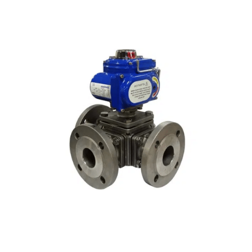
Black Ant produces electric three-way valves together with precision three-way control valves which are used in both HVAC building automation systems and light industrial process control applications. Our range is designed around open-protocol integration, so you can specify them into any BMS or SCADA platform without proprietary gateway hardware.
Electric Three-Way Globe Valves
Our electric three-way valve range delivers precise modulating control for mixing and diverting applications. Key specifications include:
- The operational scope includes diameter measurements between DN15 and DN100.
- The system can handle two pressure levels which are PN16 and PN25 that correspond to 1.6 MPa and 2.5 MPa respectively.
- The available actuator options include AC220V and DC24V and 4–20mA and 0–10V.
- The system supports communication through three protocols which are RS485 and Modbus RTU and BACnet MS/TP.
- The system provides two body materials which include brass and stainless steel.
- The organization holds three certifications which are CE and RoHS and ISO 9001 manufacturing.
The specified trim delivers two different flow characteristics which include equal-percentage flow and linear flow while providing consistent control when used with proportional temperature controllers.
Electric Three-Way Ball Valves
For on-off diverting and switching applications, our electric ball valve line includes L-port and T-port configurations. The quarter-turn actuators deliver 2–5 second stroke times for rapid response. They’re ideal for equipment switching, bypass isolation, and utility routing.
Integration with Building Energy Management
All Black Ant three-way valves integrate directly into building energy management systems via standard protocols. There’s no need for proprietary gateways or custom register mapping. If your BMS speaks Modbus or BACnet, our valves plug in natively.
Need help sizing a three-way valve for your next project? Contact Black Ant’s applications team → for Kvs calculations, actuator selection, and protocol integration support.
Conclusion
The application of three-way valves requires more effort than their basic design explains. The three-way valve mixing vs diverting distinction comes down to this: mixing valves merge two streams into one; diverting valves split one stream into two. The system controls through globe valves which provide exact control, ball valves which enable rapid operation, and plug valves which withstand extreme fluid conditions.
The next section presents essential points which you should bring to your upcoming specification work.
- The system design requires that you select the appropriate valve function which includes mixing to combine materials and diverting to create a bypass path.
- The authority requirements need two factors for sizing which include high ΔP (> 40%) in mixing and low ΔP (~20%) in diverting.
- A mixing globe valve should never be used with reverse piping to function as a diverting valve.
- A hydronic loop should not have 2-way valves and 3-way valves installed together in the same direct path.
- Use globe valves when you need to control the flow through modulating control and choose ball valves when you need to execute on-off control.
- The modern BEMS system needs open-protocol actuators which use Modbus and BACnet as specifying requirement for system integration.
The three-way valves will provide you with stable control and a long operational life and silent mechanical rooms if you correctly implement these fundamental aspects. The process will require your return to the site because you need to investigate the chattering plug which will occur three weeks after you completed the handover.
If you’re specifying three-way mixing vs diverting valves for an HVAC or process automation project, Black Ant’s engineering team can help with valve sizing, Kvs selection, and BMS integration. Request a quote or technical datasheet → and we’ll get back to you within one business day.







