

Level Gauge Calibration and Maintenance for Industrial Tanks: A Field Engineer’s Guide
The first Monday of October 2023 marks the day when Marcus Chen recalls his chemical storage tank eruption which happened because the level gauge lost its correct reading by 18 centimeters during the six-month period. His facility spent $47,000 to clean up the incident while it took three weeks to complete environmental reporting. The incident made him understand the mandatory knowledge which all field engineers must acquire because level gauge calibration and maintenance activities require actual work beyond administrative tasks. The process determines whether operations will run smoothly or lead to expensive operational interruptions.
People who work with industrial tank maintenance already understand what they must lose for their work. Uncalibrated level transmitters create four dangerous outcomes which include tank overfilling and pump dry running and tank inventory loss and regulatory body breaches. The calibration method you use needs to match the specific equipment which includes non-contact radar gauges and ultrasonic sensors and guided wave radar probes. The incorrect procedure execution will lead you to spend several hours competing against nonexistent measurements.
The guide provides field-tested calibration and maintenance instructions which cover all three level measurement technologies. The dry calibration method teaches you how to activate radar gauges through tank commissioning without needing to drain the tank while ultrasonic sensor cleaning procedures maintain their operational accuracy and echo-mapping methods in guided wave radar systems prevent false detection. Everything has been designed for immediate on-site implementation through checklists which users can access via tablets and printed documents.
Want the right instrumentation before you start? Explore Black Ant’s radar level gauge range for non-contact tank measurement with 4-20mA, HART, and RS-485 output options.
Why Calibration and Maintenance Matter for Industrial Tanks

Industrial tanks serve as storage facilities for crude oil chemicals potable water and food-grade syrups. The level gauge provides continuous data on material storage for all cases. The system experiences rapid failures when data starts to drift from its normal state.
The Real Cost of Measurement Drift
The system does not provide a detection alarm for measurement drift. The process begins to develop when antenna contamination and temperature fluctuations and process medium dielectric changes start to take effect. The diesel fuel radar gauge will maintain correct readings at installation but will experience measurement errors as vapor conditions change throughout the year. The wastewater tank’s ultrasonic sensor will experience decreased sensitivity because of biological film accumulation on the transducer face.
The financial impact shows a great degree of importance. According to process industry maintenance data, poorly maintained level sensors contribute to 15-20% of unplanned tank system downtime. Custody transfer operations experience substantial financial losses through invoice disputes which occur because of 1% level measurement errors that result in tens of thousands of dollars in monthly losses. Safety needs equal protection. Overfill prevention systems depend on accurate level data, and many jurisdictions now mandate documented calibration records for tanks above certain capacities.
How Technology Dictates Your Maintenance Approach
The level measurement technology you choose leads to distinct failure modes, which require you to establish level gauge calibration and maintenance programs that suit each instrument type.
- Non-contact radar has no moving parts and does not touch the process medium. The primary maintenance requirement for this system involves maintaining the antenna’s cleanliness and conducting routine checks on its echo-curve performance.
- Ultrasonic level transmitters require operators to maintain clean transducer equipment and monitor stable vapor conditions for proper operation. Their enemies are foam and dust and temperature gradients.
- Guide wave radar (GWR) equipment transmits microwave signals through its dedicated probe system. The long-term accuracy of the system depends on three factors, which include the intact probe structure, the correct vertical orientation and the ability to filter out false echoes created by the tank’s internal components.
The ability to recognize these distinctions enables you to plan appropriate inspections and select suitable calibration instruments while preventing the widespread error of implementing standard procedures.
Pre-Calibration Essentials
The standardized preparation process needs to be completed before anyone can start work with a transmitter. Technicians who lack proper calibration tools and safety equipment will create operational issues for their work.
Safety First: LOTO and Hazard Assessment
The instrument must remain completely separate from the active operational system. You need to close isolation valves and depressurize impulse lines after which you should apply lockout/tagout (LOTO) procedures when working with a pressure-based transmitter. Tank operations should never allow the opening of a manway or the removal of a radar antenna when the tank maintains pressure or receives filling.
Use explosion-proof tools for tanks with flammable vapors and check if your HART communicator meets the area classification requirements. You should ground yourself prior to handling electronics while you need to check that another technician can assist during tank entry operations.
Tools You Will Need
You must collect these items before you start your ascent to the tank stairway:
- HART communicator or manufacturer configuration software
- Precision multimeter for 4-20 mA loop verification
- Laser rangefinder or steel measuring tape (minimum 30-meter range for large tanks)
- Laptop with USB HART modem (for advanced echo-curve analysis)
- Soft brush and anhydrous alcohol for antenna and transducer cleaning
- Calibration log forms with space for as-found and as-left readings
Field story: Priya Sharma used her complete equipment collection except a laser rangefinder when she performed her initial radar gauge calibration on a 12-meter solvent tank. She attempted to determine the empty distance by using a regular tape measure which she extended from the roof manway and obtained a distance that measured 8 centimeters short because the tape experienced sagging. The error resulted in a permanent level shift which required two hours of investigation work to discover. Her calibration kit now contains a laser rangefinder as standard equipment.
Know Your Instrument Technology
Check the transmitter nameplate and datasheet before starting. The 26 GHz pulse radar calibration procedure requires the same steps as the 80 GHz FMCW radar calibration but needs different false-echo mapping requirements. Ultrasonic transmitters need blind zone setup which radar systems do not require. GWR units need their probe length to be verified. The datasheet requires two minutes of reading which results in two hours of saved time for menu navigation.
Radar Level Gauge Calibration Procedures
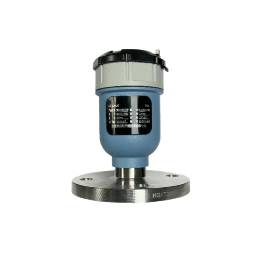
Radar level gauges, including Black Ant’s non-contact radar level gauge series, use time-of-flight measurement. The transmitter sends a microwave pulse toward the liquid surface, measures the reflection time, and converts that into a distance. Because the measurement is based on distance rather than hydrostatic pressure, radar gauges can be calibrated using a dry calibration method. You do not need liquid in the tank.
The Dry Calibration Method Explained
Dry calibration requires operators to input measurements of two separate physical distances.
- Empty distance (0% / LRV): The exact distance from the antenna face to the tank bottom or the lowest measurable point.
- Full distance (100% / URV): The distance from the antenna face to the maximum desired fill level.
The transmitter determines the measurement range through its automatic calculation system. The system transforms all distance measurements taken between these two points into a 4-20 mA signal through proportional conversion. The radar commissioning method achieves a speed increase of 60 to 80 percent because it requires only 60 to 80 percent of the time needed for hydrostatic level transmitter calibration to complete works for large tanks which need multiple 100 percent filling operations.
Step-by-Step Field Calibration
The following steps apply to all non-contact radar gauges.
- The empty distance must be measured first. The laser rangefinder should be used to measure from the antenna face to the tank bottom. The measurement must be recorded at a precision of one millimeter. The dished bottom of the tank must be measured until you reach the process-critical lowest point.
- You must enter the empty value. The HART communicator should be connected to your device which you will use to access empty calibration parameter through its interface. The finished measurement should be entered at your current location. The output should read 4.00 mA.
- The full distance measurement requires measuring the distance from the antenna face to the maximum operating level. The tank needs enough vapor space below its roof to prevent both antenna flooding and false echoes which come from the roof.
- You must enter the full value. You should enter this distance as both the span and URV measurement values. The transmitter will calculate the measurement range. The output should reach 20.00 mA when the level reaches this defined point.
- You must validate the system’s linearity. The operator should use a manual dip or sight glass to check the reading at one or two intermediate points when the tank has liquid inside. The offset requires adjustment whenever necessary.
OIML R85 mandates that high-precision applications must verify custody-transfer tank gauging systems within a limit of ±1 mm accuracy.
Echo-Curve Optimization and False Echo Mapping
The process requires you to first set both zero and span limits before you can start echo curve optimization. Technicians typically reach this point but they need to continue working to achieve higher accuracy levels.
The first step requires you to perform an initial tank scan using either the transmitter diagnostic software or HART communicator. The system will display a waveform that shows echoes which originate from the liquid surface and the internal components and the tank bottom. Your task requires you to educate the transmitter about which echo corresponds to actual level measurement.
You need to create a map that shows all permanent obstacles which include agitators and ladders and inlet nozzles and heating coils. Most radar transmitters in use today permit users to designate specific signals as false echoes which instruct the system to disregard these signals. The next step requires you to change detection thresholds until the transmitter begins to detect liquid surface echoes throughout all conditions which include foam and vapor and minor agitation.
At a Rotterdam petrochemical terminal a technician named Erik Janssen spent his entire afternoon trying to fix intermittent measurement problems which arose from a 15-meter crude oil tank. The radar system would provide accurate measurements for one hour before it experienced a sudden 2-meter jump which had no logical explanation. The echo curve analysis revealed to him that the heating coil produced a secondary echo which became visible when oil temperatures reached 70 degrees Celsius and vapor density changed. The false-echo mapping process took 10 minutes to identify the problem which three hours of recalibration had failed to resolve.
Environmental Compensation Settings
Configure these parameters if your application requires them:
- Dynamic vapor compensation: The system needs this feature to handle tanks which experience big temperature changes that alter their vapor space dielectric constant.
- Dielectric constant adjustment: The system needs this feature to handle low-ε media which includes LPG and propane and particular oils.
- The system needs still-pipe or bypass chamber compensation because the radar antenna installation occurs inside a stilling well.
Ultrasonic Level Transmitter Calibration
Ultrasonic level transmitters use the same distance measurement method which radar employs but they utilize sound waves instead of microwave technology. The system becomes more affected by environmental factors because of this design modification which requires new methods for calculating level measurements and maintaining the equipment.
Distance-Based Calibration
The calibration sequence is similar to radar:
- The first step requires measuring the empty distance from the tank bottom to the transducer face and entering the measurement.
- The second step requires measuring the full distance from maximum level to the transducer face and entering the measurement.
- The transmitter needs to establish the blind zone which represents the shortest distance from the transducer that it can measure with accurate results.
- The temperature compensation feature should be activated when the transmitter includes a built-in temperature sensor.
Ultrasonic sensors depend on the blind zone as their essential measurement component. The transmitter will stop detecting echoes when your full level measurement enters the blind zone which will result in either a fault report or a permanent maximum value display.
Maintenance-Sensitive Calibration Factors
The accuracy of ultrasonic measurements is influenced by two main factors which are the condition of transducers and the stability of their surrounding environment. Before calibration begins, you need to check these following elements:
- Transducer face cleanliness: Any coating, condensation, or crystallization on the face will absorb or scatter the sound pulse. The surface should be cleaned using a soft cloth together with anhydrous alcohol. The surface should not be scraped using any type of hard equipment.
- Perpendicular alignment: The transducer must face the liquid surface squarely. The receiver will fail to detect the echo because even a small change in angle will create an obstruction.
- Foam and vapor management: Thick foam will absorb ultrasonic energy. The increased vapor density will create reduced sound speed and false measurements which need temperature adjustments for accurate results.
The system requires a sight glass or dip reference for calibration because you cannot empty the tank. The HART communicator allows users to input actual level measurements as online offsets.
Guided Wave Radar (GWR) Calibration

The guided wave radar system transmits microwave signals through its probe which can be either a rod or a cable to reach the process medium. The design of GWR system enables it to work effectively with low-dielectric liquids and with tanks that contain foam or vapor, yet this capability requires separate calibration for each probe.
Probe-Specific Setup
The probe length must be checked against the datasheet before the calibration process can start. The vertical alignment of rod probes needs to be tested through proper alignment checking. The cable probes require verification that their cable remains correctly tensioned without making contact with the vessel’s walls. Any cable that droops or touches the wall generates false echoes which software adjustments cannot completely remove.
The manufacturer guidelines require that all extra cable length should be removed when the probe length exceeds its required measurement. The extra length should not be coiled at the bottom of the tank.
False Echo Suppression for GWR
GWR false-echo suppression focuses on probe support structures and internal obstructions near the probe. The process requires running a baseline echo curve from a tank which exists in an established state while identifying stationary echoes that remain fixed regardless of liquid height changes.
GWR calibration for oil-water separator interface measurement applications needs two liquid level settings which include total liquid level and interface position. The transmitter detects the interface because the upper and lower liquids have different dielectric constants. Interface measurement depends on probe condition more than single-liquid measurement. The system requires calibration of both upper and lower reference points to achieve accurate interface measurement.
Wet vs. Dry Calibration
GWR can be dry-calibratable when technicians possess complete knowledge of both probe length and tank dimensions. Technicians prefer to use wet calibration methods with actual process fluid because the probe presence in the liquid results in minor changes to propagation characteristics.
For wet calibration:
- The tank needs to be emptied until the zero reference point reaches the tank bottom.
- The system should be filled to 25%, 50%, 75%, and 100% of the operating range.
- At each point, the actual level needs to be recorded while the transmitter display requires adjustment to match the recorded level.
- The 4-20 mA output needs to be verified at each testing point.
Maintenance Schedules and Best Practices
A reliable level gauge calibration and maintenance program requires multiple elements to function effectively whereas calibration serves as a single component of the program. The system protects against upcoming issues through preventive maintenance which identifies upcoming problems before they develop into operational failures.
Daily and Weekly Inspections
Daily: Verify local display and remote reading against expected levels. Check that all alarms show correct operational status. Inspect the antenna housing and cable entry points for any signs of visible damage.
Weekly: Remove dirt from the antenna or transducer face. Check cable glands and junction boxes for any signs of moisture or corrosion. The operator should compare actual radar signal strength with the established baseline echo curve. The system requires antenna maintenance when signal strength decreases by 20 percent.
Monthly and Quarterly Maintenance
The schedule requires monthly trend data assessment to identify any emerging deviation from established patterns. The process requires testing both high-level and low-level alarm functions through simulation. The team needs to conduct inspections of grounding systems and surge protection equipment. The team needs to verify whether HART communication remains operational.
The guide requires organizations to conduct formal calibration verification through its established procedures. The team needs to replace existing seals and cable grommets which have reached their end of life. The team needs to update false-echo maps because new internal structures have been installed.
Technology-Specific Maintenance Comparison
|
Task |
Non-Contact Radar |
Ultrasonic |
Guided Wave Radar |
|---|---|---|---|
|
Cleaning frequency |
Weekly (antenna) |
Weekly (transducer) |
Monthly (probe) |
|
Calibration interval |
6-12 months |
6-12 months |
6-12 months |
|
Environmental sensitivity |
Low |
High (foam, dust, vapor) |
Medium |
|
Key failure mode |
Antenna contamination |
Transducer face coating |
Probe damage, build-up |
|
Best accuracy |
±1 mm |
±5 mm |
±2 mm |
Documentation and Traceability
Every calibration event shall be recorded to include the following:
- Date, name of the technician, and instrument tag number
- Any verification standard used, its calibration due date, or both
- The specific «As Found» and «As Left» readings
- Adjustments, if any, required
- Environmental conditions during calibration
Documented evidence is imperative for ISO 9001-compliance mechanism and often asked for in case of insurance and regulatory audits.
Need instrumentation that integrates into your plant monitoring system? Black Ant’s Edge Data Acquisition Computer collects 4-20mA and RS-485 signals from level transmitters and pushes data to your BEMS or SCADA platform with 10-50ms latency.
Troubleshooting Common Calibration Issues

Even with proper procedures, problems arise. Here is how to diagnose and fix the most common ones.
Erratic or Jumping Readings
The solution causes two main issues which include foam development on the liquid surface and splash production from agitators and false echoes that arise from newly installed internal structures and electrical interference.
The solution needs two steps which begin with increasing damping to reduce rapid changes and proceed to re-run false-echo mapping before checking shielding and grounding. The transducer for ultrasonic sensors needs verification to ensure its location lies outside the foam zone.
Constant Offset Error
Causes occur because of three factors: the entry of incorrect zero or span values and the zero elevation error that affects differential pressure transmitters and the temperature changes that impact capillary fill fluid.
Solutions: The HART communicator will enable us to re-trim zero and span settings. The actual fill fluid density at operating temperature will be used to recalculate zero migration for DP transmitters that use wet legs.
Signal Loss or Weak Echo
The causes of the problem happen because of three things: a dirty antenna and a damaged probe and the process medium having low dielectric constant and the system producing excessive vapor. The solutions to the problem require two actions: first, the antenna and probe need cleaning and second, the antenna type needs checking to see if it matches the medium’s dielectric constant. The system will operate better if you raise the gain to a level that stays within the limits set by the manufacturer. For severe vapor or dust, consider switching to a higher-frequency radar or a GWR probe.
Loop and Integration Problems
The 4-20 mA loop problems lead to incorrect system readings from a fully calibrated transmitter. The first step requires testing loop resistance to ensure it remains within transmitter specifications. The PLC or DCS scaling must be verified to match the transmitter’s LRV and URV specifications. The HART device requires a confirmation that its HART signal remains unblocked by both the isolator and barrier.
Black Ant Level Measurement Solutions
An excellent range of industrial instruments by Black Ant for tank level measurementd are designed for integration into existing plant control systems.
Radar Level Gauges for Demanding Applications
Black Ant’s radar level gauge series delivers non-contact measurement for tanks, silos, and process vessels. Available in 26 GHz and 80 GHz configurations, these gauges handle dust, vapor, and agitated liquid surfaces that challenge ultrasonic sensors. Output options include 4-20mA, HART, and RS-485, making them compatible with virtually any PLC, DCS, or SCADA platform.
The IP67-rated enclosure can endure outdoor tank farm installations because its non-contact design eliminates all moving components and requires only periodic antenna maintenance.
Liquid Level Transmitters for Submersible and Hydrostatic Applications
For open tanks, sump pits, and wells where top-mounting is not practical, Black Ant’s liquid level transmitters use hydrostatic pressure measurement with 4-20mA output. Submersible designs drop directly into the liquid, while flanged designs mount on the tank sidewall. These transmitters are particularly effective for water, wastewater, and chemical tank applications where radar may not be the most cost-effective choice.
Integration with BEMS and IoT Monitoring
Level data does not have to live in isolation. Black Ant’s IoT Data Collection Terminal and Edge Data Acquisition Computer can aggregate 4-20mA and RS-485 signals from multiple level transmitters and push readings to a centralized building energy management system or cloud dashboard. This enables remote monitoring, trend analysis, and predictive maintenance scheduling across your entire tank farm.
Black Ant offers complete tank storage solutions through its single radar gauge system and its full process plant level monitoring network which includes required instrumentations and system integration protocol support.
Calibration Checklist for Field Technicians

Print this checklist and take it with you on every calibration job.
Pre-Calibration Preparation
- Isolate the tank and implement LOTO
- Verify area classification and use appropriate tools
- Gather HART communicator, multimeter, laser rangefinder, and cleaning supplies
- Read the transmitter datasheet and note LRV/URV requirements
- Record baseline readings before making adjustments
Calibration Execution
- Measure and enter empty distance (0%)
- Measure and enter full distance (100%)
- Verify 4.00 mA at empty, 20.00 mA at full
- Run echo-curve analysis and update false-echo map
- Check intermediate points for linearity
- Adjust environmental compensation if needed
Post-Calibration Documentation
- Record as-found and as-left readings
- Note any adjustments made
- Update the calibration database or CMMS
- Tag the instrument with the next due date
- Report any anomalies or maintenance needs
Conclusion
The process for measuring tank levels accurately begins when organizations select appropriate technology and it finishes after they complete proper calibration and maintenance of their level gauges. Radar gauges enable you to perform dry calibration tests while reducing your need to make contact with other materials. Ultrasonic sensors function effectively in situations that maintain both cleanliness and stability but require operators to conduct thorough maintenance of transducer components. Guided wave radar functions effectively under challenging media conditions when operators keep the probe components clean and tensioned to the correct level.
The key takeaways are straightforward:
- Match your maintenance schedule to the instrument technology and process conditions
- Use dry calibration for radar and wet verification for GWR when precision matters
- Always document as-found and as-left readings for traceability
- Run echo-curve diagnostics at least quarterly to catch false echoes before they cause problems
- Verify the entire 4-20 mA loop, not just the transmitter in isolation
Black Ant provides radar level gauges and liquid level transmitters and edge data acquisition hardware for all your project specifications when you need level instrumentation for a new tank farm or retrofit project. All products are manufactured under ISO 9001 quality management and support CE marking for international deployment.
Ready to specify level gauges for your next project? Contact the Black Ant engineering team to discuss your tank dimensions, process conditions, and integration requirements. We will recommend the right measurement technology and provide full technical documentation, from datasheets to commissioning support.







