

Protecting Transmitters from Pressure Surges and Water Hammer: Ensuring the Integrity of Pressure Sensors
The combination of pressure surges with water hammer effects creates dangerous threats which decrease both the reliability and the precise functioning of pressure sensors used in fluid systems. The sudden appearance of high pressure spikes causes damage to sensors which results in incorrect measurements and leads to expensive business interruptions. Your system needs protection through proper knowledge of the causes and impacts of these phenomena which affect your equipment and operational performance. The article presents the specific methods which pressure surges and water hammer use to disrupt pressure transmitters along with the most suitable methods to reduce these dangers. The session will enable you to learn all necessary methods which protect pressure sensors while you manage your monitoring system operations.
Introduction to Pressure Surges and Water Hammer

The hydraulic phenomenon of pressure surges and water hammer occurs when a pipeline experiences sudden fluid velocity changes. The system experiences these changes when a valve closes quickly or a pump initiates or stops its operation or a system blockage happens. Pressure surges create spikes in fluid pressure while water hammer generates shockwaves that move through the entire system. The two phenomena generate extreme forces which can cause damage to pipelines and valves and pressure sensors which results in system breaks and operational downtime. People need to understand these effects because they help maintain operational stability in fluid control systems.
Defining Pressure Surges and Water Hammer
Scientists refer to pressure spikes which occur in the pipeline system when its fluid movement stops because of sudden fluid velocity changes as transient flows. Operators cause the system to experience pressure spikes through their actions of closing valves too quickly and starting and stopping pumps and facing unexpected obstacles that impede fluid movement. The three factors which determine pressure surge strength include the density of the fluid and the elastic properties of the pipeline material and the speed at which flow variations occur. The pressure surges that occur in water distribution systems reach temporary pressure peaks which reach 10 times normal operational pressure because of system dynamics and control measures.
Water hammer represents a particular type of pressure surge that comes with greater intensity. The process creates shockwaves which travel through the fluid system and move through the pipeline system whenever there is an abrupt interruption in the fluid flow. The Joukowsky equation explains this phenomenon through the equation which shows that pressure change (∆P) depends on fluid density (ρ) and wave speed (a) and fluid velocity change (∆v):
∆P = ρ × a × ∆v
The pressure increase in a standard steel pipe system which carries water can reach 60 psi when water velocity increases by 1 ft/s depending on the pipe material and wall thickness. Water hammer generates intense pressure which creates shockwave movements that result in material fatigue and structural damage and pipeline ruptures in extreme cases.
Engineers must create advanced engineering solutions which combine pressure-relief valves with surge tanks and air chambers to solve these problems. Modern systems use predictive modeling tools which apply computational fluid dynamics (CFD) to model transient system behavior across different operational scenarios thus reducing the probability of major system breakdowns. Engineers need to study fundamental physics and gather entire system data to build effective fluid control systems that can withstand different challenges.
Impact on Pressure Transmitters and Sensors
The system stop working because pressure transmitters and sensors which function as essential components for fluid control systems face operational challenges from sudden pressure spikes and hydraulic shocks and water hammer effects. The system generates high-frequency vibrations which produce mechanical forces that result in sudden pressure changes and these factors together endanger the sensors while decreasing their work duration. The following five factors affect pressure transmitters and sensors together with complete technical explanations:
① Mechanical Fatigue & Wear
Sensors lose their structural integrity because their diaphragms develop microfractures which occur during continuous pressure spikes. The computational analysis shows that all transmitter pressure surges which last longer than 150% will reduce transmitter operating time for up to 30% of its lifetime.
② Signal Noise & Data Distortion
The combination of rapid pressure changes and high-frequency oscillations creates problems because it produces significant signal noise in both analog and digital systems. The system monitoring accuracy suffers from this distortion because real-time monitoring shows a deviation range that goes beyond ±3% during intense transient situations.
③ Range Overload & Calibration Drift
When sensing elements operate outside their designated pressure limits which exceed 200% of their specified range for extended periods then their elements will sustain permanent damage. The environment requires sensors to undergo recalibration because frequent events occur which results in higher maintenance needs by 15% each year due to high-stress conditions.
④ Seal Degradation & Leakage
The sensor housing’s seals and O-rings become stressed from rapid pressure changes which creates a risk of leaks that can result in contamination. The empirical data demonstrates that pressure changes which reach 80 psi per second create a 25% increase in seal erosion.
⑤ Temperature-Induced Sensitivity Loss
Transient fluid dynamics create localized heating effects which affect the temperature coefficient of sensitivity (TCS) measurements in specific sensors. A 10°C temperature rise can decrease output accuracy by up to 0.2% in temperature-compensated models. The design process and maintenance schedule development should include these effects to achieve maximum performance while enhancing the reliability of pressure transmitters and sensors used in dynamic fluid control systems.
Understanding the Water Hammer Effect
The water hammer effect, which people also refer to as hydraulic shock, produces a pressure surge that occurs when an active fluid stream experiences instant halting or direction change. This phenomenon usually occurs in pipelines because fast valve closures and sudden pump shutdowns create conditions which disrupt fluid flow and lead to the generation of high-pressure shock waves. The pressure spikes which happen during these events create extreme structural strain on pipes and joints and equipment, which may lead to material breakdown or total system failure.
Studies indicate that the Joukowsky equation enables researchers to estimate water hammer pressure by using its mathematical formulation:
ΔP = ρ × a × ΔV
| Variable | Definition | Unit |
|---|---|---|
| ΔP | Pressure increase | Pa |
| ρ | Fluid density | kg/m³ |
| a | Speed of pressure wave | m/s |
| ΔV | Change in fluid velocity | m/s |
The pressure wave speed of 1200 m/s causes pressure surge to reach 2.4 MPa when water with 1000 kg/m³ density moves through a pipeline at 2 m/s. The system needs strong design solutions to handle the massive pressure because it creates the risk of system failure. The practical needs of the project require the installation of pressure-relief valves together with air chambers and surge tanks which will handle shock wave impacts. The design process uses advanced technology that includes computational fluid dynamics (CFD) simulations to forecast water hammer impacts during different operational conditions. The design of modern control systems enables automated systems to regulate valve functions which help control fluid flow rates for smoother transitions thus decreasing the occurrence of hydraulic shocks. Industrial case studies have established that companies need to conduct proper maintenance work which includes valve inspections and pipeline support assessments because these actions help reduce the long-term hazards connected to the water hammer phenomenon. Effective system safeguarding requires implementation of preventative techniques which need to include advanced knowledge about fluid transport systems. The system will maintain both structural stability and operational performance through these techniques.
Technical Causes of Pressure Surges

The pressure surges which result from the water hammer effect occur when water flow inside pipes experiences sudden speed changes. The water flow system experiences these surges because of three specific operational events which include closing valves and starting or stopping pumps and making abrupt changes to flow direction. The following factors serve as primary reasons for pressure surge occurrences.
- 1
Valve Operations
The system experiences pressure wave expansion when operators execute immediate valve operations which involve either closing or opening valves. The process of closing a valve before a pressure wave completes transmission results in shock wave production which generates pressure increases that can be calculated using the Joukowsky equation ΔP = ρ·c·Δv (where ρ is the fluid density, c is the wave speed, and Δv is the velocity change). Studies show typical water hammer pressures can range from 2 to 10 times the operating pressure. - 2
Pump Systems
The process of starting or stopping a pump creates temporary flow conditions which have the potential to produce pressure spikes. The research demonstrates that when centrifugal pumps trip in pipelines the system undergoes immediate decompression which leads to overpressure conditions that can reach more than 150 psi when surge tanks and other dampening systems are not present. - 3
Pipeline Fittings & Directional Changes
The use of elbows and tees and similar fittings enables fluid redirection which creates points of increased pressure during the flow process. The researchers used computational fluid dynamics (CFD) simulations to establish that pressure upstream of sudden directional shifts will increase by up to 25% based on the width of the pipeline and the speed of the fluid. - 4
Absence of Cushioning Systems
The absence of proper cushioning systems which include surge suppressors or air chambers makes all systems more vulnerable to pressure transients. The recent reports show that pipelines with air valves which had improper calibration experienced pressure excursions that caused material fatigue and led to pipeline rupture.
The technical factors of the system create excessive stress on pipelines which leads to material failure and results in total system breakdowns when these technical factors remain unaddressed. The prediction and control of pressure events require the use of hydraulic modeling tools together with advanced diagnostic systems and monitoring systems that operate in real time.
Hydraulic Dynamics and Pressure Spikes
The study of hydraulic dynamics serves as an essential method for analyzing pressure spikes which occur during pipeline system operations because it helps to identify pressure changes that happen during transient events which include both pump startups and valve closures and sudden flow interruptions. Pressure spikes which people also call water hammer events happen because a fluid experiences sudden velocity changes that create shock waves which move through the liquid. The phenomenon causes pressure to increase substantially and the measurement system uses pounds per square inch (PSI) which can reach levels that exceed the operational limits for pipeline equipment.
Studies indicate that pressure waves from water hammer events can travel at speeds approaching 4500 feet per second through metallic pipelines because the fluid type and pipe material and system configuration determine their movement speed. A 10-inch steel pipeline simulation derives its results from the Moody Chart and Joukowsky equation which shows that the pipeline will experience pressure oscillations between 120 PSI and 300 PSI when a valve closes rapidly. The uncontrolled dynamic stresses will cause joint fatigue and gasket failures and catastrophic rupture.
Engineers now depend on data-driven methods and advanced computational tools to reduce risks. AFT Impulse and Bentley Hammer both serve as hydraulic modeling software which enables users to create accurate simulations of transient hydraulic behavior. The system uses pipeline geometry and fluid compressibility and wave speed as input parameters which help assess pipeline vulnerabilities before actual system failures occur. The system uses distributed sensor networks to monitor pressure changes in real time which enables continuous pressure monitoring throughout the system. Operators use pressure transducer data and flow meter data to quickly handle safety risks while they maintain essential system functions.
The rising access to comprehensive research studies together with advanced diagnostic tools demonstrates the necessity of implementing preventive measures which handle pressure transients according to established industry standards and governmental regulations. The use of predictive modeling together with strong monitoring systems lets organizations manage transient events which leads to fewer operational disruptions and better system performance.
Common Sources of Pressure Surges
The term pressure surges which people also call hydraulic transients and water hammers describes sudden pressure fluctuations which occur in fluid systems because of multiple operational and external disturbances. System integrity maintenance depends on understanding these sources which help develop effective mitigation strategies.
| Source | Description & Key Data |
|---|---|
| Pump Start & Shutdown | Pressure waves travel through system components when operators start or stop pumps because this process creates an abrupt change in flow velocity. Recent studies show that pressure spikes during such situations can increase to 10 times normal operating pressure because system configuration and pipeline material determine pressure limits. |
| Valve Operations | Pipes experience their most significant pressure fluctuations when operators execute valve closures that they perform incorrectly or execute suddenly. The 2021 industry analysis found that valve operation causes about 45 percent of pressure transients which occur in water distribution systems. |
| Power Failures | Power outages which occur suddenly create uncontrolled backflows and pressure spikes because they cause pumps and other active components to shut down unexpectedly. A case study conducted in a large municipal pipeline network showed that power loss in pumping stations created surges which reached 8 bar exceeding the design pressure of various system components. |
| Air Entrapment & Release | Air bubbles that become trapped inside pipelines create higher pressure levels which occur during their compression phase and their subsequent release phase. The computational fluid dynamics (CFD) models show that even small amounts of air introduce pressure increases between 20 and 30 percent above normal operating conditions. |
| Pipeline Breaks & External Damage | Excavation accidents which cause pipe bursts and pipe breaks together with mechanical failures lead to immediate shifts in pipeline pressure. The field data gathered from repair operations shows that pressure can drop to -5 bar which creates conditions for cavitation to occur and secondary damage to auxiliary equipment. |
| Turbulent Flow Transitions | High-velocity systems experience flow instability which occurs when their flow patterns change from laminar to turbulent flow. The recent research findings about oil and gas pipelines demonstrate that changes to the flow regime lead to system stress because of multiple high-frequency pressure fluctuations which cause system components to vibrate. |
The pressure surge phenomenon requires complex analysis from all these sources to understand its underlying dynamics. The system needs real-time monitoring together with predictive analytics to identify critical events and prevent them from becoming problems.
Factors Leading to Water Hammer
The occurrence of water hammer results from abrupt changes that take place during fluid movement within piping systems. The assessment of water hammer origins requires researchers to understand all elements which contribute to its development because this knowledge will assist them in creating successful management methods. The five factors that affect water hammer are explained through their specific details.
- 1.
Sudden Valve Closure or Opening
Valves which close or open their positions without delays create sudden changes in flow rate which results in pressure surges that move through the entire system. Research shows that pressure spikes can reach up to 10 times the normal operating pressure depending on the duration and speed of valve actuation. - 2.
Pump Start-Up or Shut-Down Events
Pump operations experience flow turbulence during all transitional moments which include both starting and stopping times. The immediate shutdown of pumps results in fluid flow deceleration which causes reverse flow and pressure transients that create stress on pipeline systems. - 3.
High Flow Velocity
Any sudden flow interruption increases the possibility of pressure shocks when fluid velocities reach their highest levels. Research shows that hydraulic systems experience greater water hammer effects when they operate at speeds above 10 ft/s than when they maintain standard flow rates. - 4.
Air Entrapment in Pipes
Air pockets inside the pipes create pressure surges which affect the liquid-filled pipes. The air pockets create shock waves which result in more severe water hammer events when they get compressed or moved because they contact the flowing fluid. - 5.
Improper Pipe Design or System Layout
The system faces greater problems because pressure transients become worse through design defects which include unsupported pipe sections that extend for long distances and system bends which create sudden changes in direction. The Computational fluid dynamics (CFD) simulations demonstrate that systems which lack proper design experience pressure increases which surpass 1.5 times their expected design pressure during water hammer incidents.
The operational lifespan of fluid transport systems depends on specific factors that need to be understood because they help prevent infrastructure destruction. Organizations need to conduct detailed analysis together with system-specific interventions which will help them effectively reduce water hammer risks.
Risks to Pressure Transmitters
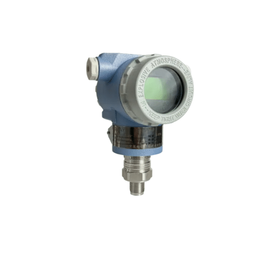
The pressure transmitters face their greatest danger from water hammer because this phenomenon creates sudden pressure fluctuations and pressure surges. The sensor experiences pressure changes which occur at high speeds, these changes result in mechanical stress and loss of accuracy and total equipment failure. The water hammer events create pressure levels which exceed the system’s normal operating range by two to three times its maximum designated pressure limit. According to a technical study from 2021, transient pressure spikes caused over 60% of early pressure transmitter failures which occurred in fluid systems.
The water hammer vibration creates transmitter diaphragm and internal component fatigue, which results in accelerated device degradation. The industry standards show that continuous exposure to vibrations above high frequencies can decrease pressure transmitter lifespan by more than 30 percent. The design of system piping networks which lack effective damping solutions creates a major risk for the system.
Surge suppression devices and pressure snubbers serve as protective solutions, which maintain system pressure stability throughout sudden pressure changes until equipment reaches its operational threshold. Pressure transmitters that operate in dynamic pressure applications need protection against both shock and vibration to function properly in these demanding conditions. The system needs both ongoing maintenance work and permanent monitoring activities to find pressure anomalies at their highest efficiency.
Vulnerability of Pressure Gauges to Surges
The design limitations of pressure gauges make them susceptible to sudden pressure spikes which occur because their internal parts are built with fragile components that cannot withstand sudden pressure changes. The system experiences severe operational and mechanical destruction which results from sudden flow rate alterations and system failures. Below are five primary vulnerabilities of pressure gauges when exposed to pressure surges:
| Vulnerability | Effect on Gauge |
|---|---|
| Mechanical Deformation | Pressure surges produce permanent deformation of the internal gauge components which includes the Bourdon tube and diaphragm and capsule. The deformation of the internal components of the gauge will result in either reduced accuracy or complete operational failure of the device. |
| Overpressure Damage | The pressure range of gauges defines their operational limits which they can safely measure. The device will fail when pressure surges exceed these limits because the overpressure threshold has been breached which causes seals to break and leakage to occur and the entire device to malfunction. |
| Fatigue Failure | Internal material fatigue develops when spring elements present in the material undergo repeated pressure surge exposure. The gauge starts to lose its structural strength which leads to critical failures and operational loss. |
| Reduced Measurement Accuracy | Pressure surges lead to temporary or permanent loss of pressure gauge calibration which causes the gauge to produce incorrect measurements. The resulting measurement inaccuracies create a threat to both system safety and system reliability. |
| Internal Vibrational Damage | Pressure surges generate intense vibrations which result in internal gauge components becoming loose or damaged. The operational components undergo a process of deterioration which leads to decreased efficiency and an increased need for regular calibration and component replacement. |
Consequences of Water Hammer on Sensors
Water hammer causes sensor issues and shortens sensor lifespan in fluid systems. The subsequent part evaluates five main consequences which arise from water hammer.
- Sensor Membrane Damage
Water hammer creates high-pressure spikes which have the potential to either bend or break sensor membranes. The essential elements need to function correctly which requires them to maintain their operational state because any damage will lead to major system failures that cause operational delays. - Signal Distortions
The pressure changes which occur during water hammer create unstable data outputs for the sensor. The monitoring system creates measurement errors because it shows distorted results which cannot achieve real-time accuracy. - Reduced Measuring Range Accuracy
The sensor will experience permanent calibration alterations from multiple instances of pressure surge exposure. The measurement accuracy will decrease throughout the entire range which results in the need for either sensor recalibration or complete sensor replacement. - Electrical Component Failure
The sensitive electronic circuits inside sensors which have built-in electronics become exposed to high danger from transient pressure surges which can either break or damage their components. The device will experience erratic output behavior or complete operational failure. - Accelerated Wear on Seals and Housings
The sensors experience repeated stress from water hammer which creates shock waves that impact their seals and housings. The sensor experiences fluid leakage and instability because of this continuous process which ultimately results in system failures and increased maintenance expenses.
Long-term Effects of Pressure Spikes
The combination of pressure spikes caused by water hammer effects and unexpected fluid flow changes creates multiple permanent impacts on industrial operations and their machinery. The following five effects demonstrate how different risks can cause various types of damage.
| Long-term Effect | Technical Detail & Data |
|---|---|
| Material Fatigue & Structural Cracking | The pressure changes which pipelines and valves experience throughout their operational life begin to affect all system components. Through material fatigue the material undergoes stress which develops microscopic cracks that eventually result in catastrophic failures. The material life of items decreases because of repeated pressure spikes which lead to steel components now experiencing increased wear rates that reach 30%. |
| Pipeline Distortion & Misalignment | Pipelines experience bending or misalignment because of dynamic forces which result from pressure spikes. The operational process faces difficulties because the distortion leads to damage of joint connections and mounting brackets which creates leaks and hinders fluid transport. The pipeline alignment deflection reaches 2 to 3 degrees through multiple years because of longitudinal stress which results from repeated pressure waves. |
| Erosion-Corrosion Acceleration | The pressure spikes create conditions which lead to fast fluid flow that increases internal surface erosion during the events. Corrosive fluid components combine with the process to damage pipeline walls and sensor housings. Research shows that systems which process abrasive fluids experience erosion-corrosion rates that increase by 40% when they operate in high-pressure fluctuation environments. |
| Premature Valve & Rotating Equipment Failures | Valves and rotating machinery systems which include pumps and turbines face operational wear problems because their design needs to handle pressure spikes which create challenges for their systems. The process of repeating valve operations causes intense pressure which results in valve seat damage and internal seal breakdown that finally leads to complete system failure. Rotating equipment faces random surges which result in shaft misalignment problems and bearing failures that require complete system reconstruction within six months from its projected operational life. |
| Decreased Measurement Accuracy in Instrumentation | Pressure sensors and flow meters need stable operational environments to deliver precise measurement data. Continuous pressure spikes during operation will destroy sensors because they cause internal component damage which creates measurement errors through signal drift and signal noise. Empirical studies have documented accuracy deviations of up to 5-10% after extended exposure to pressure surges which significantly endanger process control efficiency. |
The system design needs to establish active control systems which require both surge tank systems and pressure wave dampening equipment together with scheduled maintenance work to minimize upcoming threats that might arise.
Best Practices for Protecting Pressure Sensors

🛡️
Install Surge Protection Devices
Most sensor damage occurs because pressure surges which people call pressure transients create unsafe conditions. The installation of surge tanks and pressure dampeners results in better pressure control which prevents equipment damage and extends equipment life. The research shows that these devices can achieve an 80% reduction in pressure fluctuations which leads to better system stability.
🔬
Schedule Calibration Procedures
The pressure sensor maintains its highest accuracy through routine calibration which handles both environmental changes and time passage. Pressure sensors need calibration every six months according to industry standards but high-stress situations require more frequent calibration to control measurement errors.
⚙️
Choose Materials for Intended Use
Sensors require stainless steel and Hastelloy as corrosion-resistant materials because they must withstand extreme chemical and saline conditions. The research shows that this method can extend durability in corrosive environments by 40% while also preventing unintentional equipment breakdown.
🌡️
Establish Temperature Compensation
Temperature changes create operational problems for sensors because thermal expansion and contraction cause their performance to decline. The advanced systems which include temperature compensation elements show a 90% reduction in measurement errors which enables consistent monitoring across multiple operational conditions.
📋
Create Preventive Maintenance Schedule Systems
Proactive maintenance tasks include visual inspections and cleaning and functional testing which help to detect initial stages of equipment deterioration. The maintenance program which uses data analytics to support its operations has shown improved operational efficiency through reduced unexpected downtime.
Implementing Snubbers for Pressure Protection
Snubber systems serve essential functions to protect pressure-sensitive control systems because they protect those systems from sudden pressure changes that occur between 19 psi and 21 psi. The system uses pressure drop control to safeguard sensitive equipment, which includes gauges and transmitters and pipelines, from damage that occurs during transient pressure fluctuations. The process of installing snubbers creates controlled flow restrictions, which absorb sudden pressure spikes, thereby increasing the operational lifespan of measurement and control systems.
Current studies demonstrate that snubber application in high-pressure environments generates pressure spikes that decrease about 80% because of specific system design parameters and actual operating conditions. The hydraulic system functions at its highest pressure, which reaches 3000 psi, while snubber devices maintain their correct calibration to protect equipment from failures and ensure measurement results remain within accepted accuracy standards. Industries that operate equipment with pulsating functions, such as reciprocating compressors and pumps, have achieved a 70% drop in gauge failures through their implementation of high-quality snubbers.
The material composition of snubbers needs to match both the operating fluid and environmental conditions. The corrosive environments require stainless steel snubbers, while high-pressure applications need the same material, and brass units operate best with low to moderate pressure systems. The capacity of a snubber orifice to perform under specific conditions depends on its fixed or adjustable design, which requires matching the pulse frequencies that exist within the system.
| Snubber Material | Best Application |
|---|---|
| Stainless Steel | Corrosive environments and high-pressure applications |
| Brass | Low to moderate pressure systems |
The complete integration process of snubbers depends on engineers who need to perform analysis work while selecting specifications and managing maintenance activities, which safeguard equipment against particle accumulation that results in system failures. Organizations can enhance their pressure-sensitive system reliability by implementing these factors, which result in safer operations and superior efficiency.
Using Siphons to Mitigate Water Hammer
Water hammer describes a hydraulic effect which results from abrupt changes in fluid movement through pipelines. The implementation of siphons functions as a crucial technique which helps to decrease negative impacts by controlling the speed at which water moves through systems. Siphons create controlled conditions for fluid movement by using elevation changes which allow them to prevent sudden pressure fluctuations. The recent research demonstrates that well-built siphon systems decrease pressure by 70 percent through different combinations of pipe materials and pipe diameters and fluid velocity system parameters. Siphons which use gradual slope transitions and proper venting systems show effective performance in high flow rate systems which exceed 3 m/s.
Siphons function together with air chambers and surge tanks to enhance pressure wave suppression through their extra protective functions. The Computational Fluid Dynamics (CFD) simulations show that high-pressure systems which use siphons experience shockwave delays of up to 50 milliseconds which protects pipelines from structural damage. Siphons require specific design elements which include proper fluid property accommodation through viscosity and density specifications and design standards which require smooth surfaces to decrease turbulence and ASME B31.3 pressure piping system standards. The system needs ongoing maintenance and evaluation because siphon control problems stem from airlock creation and sediment buildup and equipment corrosion.
Siphons operate as a cost-effective solution which industries use to implement water hammer control because their design protects hydraulic systems in applications that require dependable equipment operation.
Seal Systems: A Barrier Against Pressure Damage
Industrial applications and hydraulic systems use seal systems to function as essential parts which block fluid movement while stopping leaks and protecting their equipment from pressurized system failures. The system design permits them to function under multiple operational conditions which include different pressure levels and temperature ranges and various chemical substances. Recent research shows that mechanical seal failures cause 40 percent of pump failures which occur in industrial operations thus demonstrating the critical need for strong seal designs and appropriate maintenance procedures.
The current seal systems create mechanical seals and labyrinth seals and magnetic seals using contemporary materials which include carbon graphite and silicon carbide and elastomers. Mechanical seals used in oil and gas operations receive design specifications which enable them to handle pressures above 1,500 psi and temperatures above 500°F because these conditions arise from operating high-pressure pipelines and handling volatile chemicals.
The industry reports show that using high-quality seal systems brings significant economic advantages to businesses. The research shows that advanced seal technology implementation helps businesses cut their operational expenses between 10 and 15 percent because it decreases unplanned equipment failures that lead to production stoppages. Equipment monitoring through seal systems gained advanced capabilities which use predictive maintenance sensors to identify early signs of equipment deterioration and pressure changes thus allowing operators to make necessary equipment adjustments that will extend equipment life.
The combination of high-performance seal systems and systematic inspection procedures and scheduled maintenance activities provides complete protection for industrial processes which operate in energy and pharmaceutical and water management industries.
Maintenance and Preventative Measures
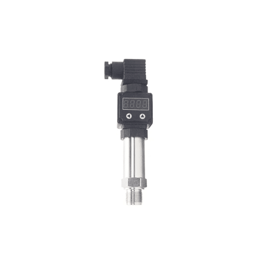
All industrial equipment needs regular maintenance together with preventive maintenance methods to keep functioning properly. Advanced techniques combined with data-driven approaches enable organizations to achieve superior operational outcomes because these approaches reduce equipment downtime while enhancing operational efficiency and preventing costly breakdowns. The following five strategies represent essential elements of maintenance activities and preventive operations:
- 1.
Scheduled Preventative Maintenance
The scheduled maintenance checks and servicing work will verify that components function according to their established operating limits. Studies demonstrate that when organizations use preventative maintenance their operations experience 30 percent less downtime compared to their reactive maintenance approach. - 2.
Condition Monitoring
The combination of vibration analysis and thermal imaging plus ultrasonic testing generates equipment health information for real-time monitoring. Condition monitoring enables the identification of 95% of mechanical failures before they actually happen. - 3.
Lubrication Management
The correct lubrication methods require professionals to track both viscosity and contamination levels because these factors will help them reduce friction and material degradation. The research shows that more than half of bearing failures in industrial machines happen because of incorrect lubrication practices. - 4.
Employee Training and Standardized Protocols
Operators and maintenance personnel need thorough training on procedure and equipment operation to prevent human error which causes 23% of industrial accidents. The standardized maintenance procedures help organizations achieve compliance while executing their maintenance activities efficiently. - 5.
Predictive Analytics and IoT Integration
The combination of Internet of Things devices with predictive analytics tools enables organizations to predict equipment aging and component degradation more accurately. Organizations experience 15 to 20 percent operational efficiency improvements after they implement IoT systems that support maintenance planning through forecast capabilities.
The implementation of these complete measures will enhance industrial operations while maintaining equipment performance and safety throughout time.
Regular Inspection and Testing Protocols
The maintenance process of industrial systems needs regular testing and inspection procedures which serve as vital components for maintaining their operational integrity. The testing procedures require these scheduled assessments to determine equipment status which includes identifying wear and impending failure and performance decline before these issues lead to operational disruptions or safety hazards. Companies that maintain regular inspection programs achieve up to 25% decrease in unexpected equipment failures according to industry reports.
Current inspection techniques employ non-destructive testing (NDT) methods which utilize both ultrasonic testing and radiographic testing and thermal imaging. Technicians use ultrasonic testing as a testing method to detect internal material defects which include cracks and voids with an accuracy rate of more than 90%. Digital twins now serve as virtual testing environments which enable users to conduct real-time simulations that predict how assets will perform under different operational scenarios.
The research findings demonstrate that organizations which implement both IoT monitoring systems together with regular inspection practices experience improved operational efficiency. IoT sensors provide continuous monitoring for essential metrics which include temperature and vibration and pressure that generate usable information throughout the entire day. IoT-based predictive inspections implementation in surveyed industries during 2022 resulted in 30% increase of overall inspection accuracy together with 15% decrease of inspection expenses.
AI-powered analytics now expedite the inspection procedure through their ability to evaluate past data for upcoming maintenance needs. The inspection schedule uses data analysis to determine optimal inspection times which prevent equipment from receiving both excessive and insufficient maintenance. The implementation of structured technology-based inspection systems enables organizations to extend equipment durability while decreasing operational disturbances and maintaining strict safety standards.
Strategies for Routine Maintenance of Pressure Sensors
Maintenance of pressure sensors needs regular procedures which ensure their accurate operation, their reliable performance and their extended operational life. The five strategies presented below contain data-backed methods which use specialized knowledge to support their implementation.
| Strategy | Details & Supporting Data |
|---|---|
| Regular Calibration | The calibration requirements for pressure sensors need to be scheduled according to actual usage patterns and operational performance metrics. Studies show that regular calibration procedures can boost measurement accuracy through a maximum 15% gain. Employers need to use traceable calibration standards which help them follow industry regulations while their equipment performs consistently. |
| Inspection for Physical Damage | Inspectors need to conduct complete visual assessments which enable them to detect any damages through their process of checking for corrosion and cracks and leaks that affect sensor housing or connections. According to industry data, up to 20% of pressure sensor failures in industrial environments are attributed to physical wear and tear that could have been detected early. |
| Environmental Condition Monitoring | The sensor requires proper environmental conditions which include maintaining specific temperature and humidity and pressure levels to stop component deterioration. High-temperature environments, for instance, can cause sensor drift over time. Data indicates that optimal condition maintenance will extend sensor operational life by 30%. |
| Cleaning of Sensor Components | The sensors need cleaning because their accuracy depends on clean sensors which most tests require. The cleaning process needs suitable materials and methods because they protect delicate parts from damage. The cleaning schedules which organizations implement show a 25 percent reduction in sensor performance issues at locations which experience heavy dust contamination. |
| Verification of Electrical Connections | The process requires inspection of electrical connections which must be secured to prevent any interference with signals and loss of data. Pressure sensors malfunction in 15 percent of cases because of connections which become loose or corroded. The organization uses diagnostic tests to perform electrical system checks which help them identify and fix data transmission errors. |
The systematized implementation of these strategies enables operators to achieve three goals which include reducing sensor downtime and improving measurement reliability and increasing operational efficiency.
Identifying and Addressing Potential Issues Early
The pressure sensors require immediate problem detection and solution implementation to maintain their performance accuracy and increase their operational lifespan. The system maintains dependable operation through its maintenance schedule and its proactive diagnostic system which protects against unexpected system failures. The next section describes five common problems which occur together with their corresponding solutions.
| Issue | Description & Data | Recommended Solution |
|---|---|---|
| Sensor Drift | Sensor drift results in approximately 20% of long-term operational readings which the industry considers inaccurate. | Regular calibration at specific time intervals. |
| Environmental Extremes | Extreme environmental conditions lead to material degradation which results in about 25% of sensor failures. | Use sensors containing durable materials like stainless steel and special protective coatings. |
| Overpressure Damage | Overpressure events account for 12 percent of all sensor malfunctions which take place in industrial settings. | Install pressure relief valves together with overload protection systems. |
| Electrical Noise Interference | Interference is identified as a factor in 8% of measurement inaccuracies. | Use shielded cables and proper grounding techniques to maintain signal transmission quality. |
| Improper Installation | Misinstallation problems account for 10-15% of all initial sensor malfunctions. | Implement manufacturer specifications together with post-installation assessments. |
The implementation of specific solutions for these common problems enables operators to achieve dependable pressure sensor performance which results in extended sensor lifespans and continuous efficient system operation.
Frequently Asked Questions (FAQ)
References
- Water Hammer In Piped Water Distribution System: Investigation In Practical System And Protection Scheme PDF Link
- Numerical Investigation and Analysis of the Pipes’ Pressure in Water Transmission Lines PDF Link
- Introduction to Pressure Measurement PDF Link
Protecting your pressure sensors from surges and water hammer is an investment in long-term system reliability, measurement accuracy, and operational safety. Implement the strategies outlined here to ensure your fluid systems perform at their best.







