Implementing IoT Data Acquisition Terminals for Real-Time Building Monitoring
The Internet of Things data acquisition terminal functions as the main control system for your building. It collects data from all installed sensors and meters and valve systems. The system performs processing tasks on the edge network. It transmits only essential information needed by your management dashboard. The building operates without direction because it lacks this functionality.
Facility managers today face a growing problem. The organization needs to track its HVAC systems and smart meters and multiple vendor controllers which currently exist as separate systems. The organization stores data in separate locations which create problems. The system sends notifications to users at insufficient times. Energy waste continues to grow because people cannot access complete information.
An IoT data collection terminal solves this. It bridges old and new equipment, aggregates multiple protocols, and delivers real-time visibility from a single interface. This guide walks through selecting, installing, and commissioning an IoT data acquisition terminal for real-time building monitoring. Whether you manage a commercial office, a district heating network, or a smart city deployment, these steps apply.
What Is an IoT Data Acquisition Terminal?
The Role of the Terminal in Modern Building Automation
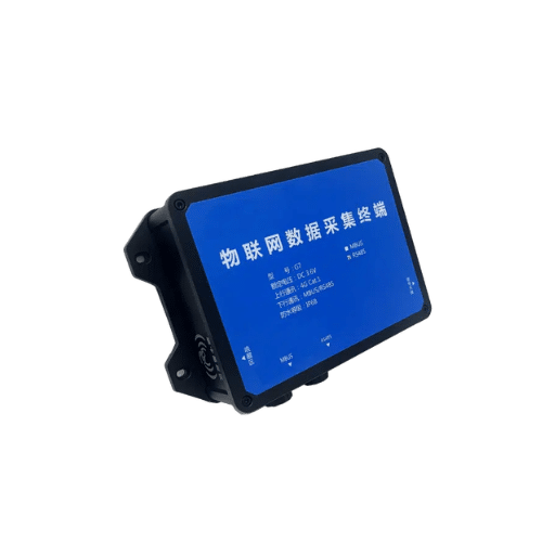
What is an IoT data acquisition terminal? An IoT data acquisition terminal functions as an edge device which gathers data from field-level sensors and meters and forwards it to a central building management platform. The system operates as a protocol translator which also functions as a data aggregator to provide real-time monitoring of building automation systems that use multiple vendor solutions.
The system functions as a translator and traffic controller which connects your sensors to your building energy management system (BEMS).
Modern building automation uses a four-layer technology stack which includes:
- Field devices — sensors, meters, valves, and controllers which generate raw data
- The IoT data acquisition terminal functions as an edge device which collects and preprocesses data signals
- The edge or cloud platform serves as the location for advanced analytics and storage and remote access capabilities
- The dashboard or BEMS system provides operators with an interface to monitor and control and enhance operational efficiency.
The terminal is what makes this stack work. Without it, you would need separate gateways for every protocol, separate cables for every device, and separate software interfaces for every subsystem. A well-designed terminal — such as Black Ant’s Edge Data Acquisition Computer — handles multiple protocols in one enclosure. It can read RS-485 Modbus registers from a heat meter, capture 4-20mA signals from a pressure transmitter, and forward everything over 4G or NB-IoT to your cloud platform.
Edge Computing vs. Cloud Computing for Real-Time Monitoring
Not all data needs to go to the cloud. In fact, for real-time monitoring building automation workloads, edge computing is often the smarter choice.
|
Factor |
Edge Computing |
Cloud Computing |
|---|---|---|
|
Latency |
10–50 ms |
100–500+ ms |
|
Bandwidth |
Low (only insights sent) |
High (all raw data streamed) |
|
Reliability |
Works offline, buffers locally |
Requires constant connectivity |
|
Cost |
Lower ongoing data fees |
Higher data transmission costs |
|
Best for |
Real-time control, safety alerts |
Long-term analytics, reporting |
Here’s why this matters. If a district heating pipe loses pressure, you need an alert in milliseconds — not seconds. An edge data acquisition computer can process the signal locally, trigger an alarm, and shut down a pump before the anomaly ever reaches the cloud. It also buffers data during network outages, so you never lose historical records. Cloud computing has its place for trend analysis and remote dashboards. But for real-time building monitoring, edge-first architecture is the more reliable default.
Key Protocols and Connectivity Options for IoT Data Acquisition Terminals
Field Protocols: Modbus RTU, BACnet MS/TP, and M-Bus
Your devices use protocols as their communication methods. The six key protocols for IoT data acquisition in buildings are:
- Modbus RTU — industrial HVAC communication over RS-485
- BACnet MS/TP — building automation standard in North America and Europe
- M-Bus — utility metering communication (EN 13757)
- MQTT — lightweight messaging for cloud uplink
- LoRaWAN — long-range low-power wireless for outdoor sensors
- NB-IoT — narrowband cellular for remote meter reading
The three most common field protocols are Modbus RTU BACnet MS/TP and M-Bus.
A Modbus RS485 data acquisition terminal is the workhorse of industrial and HVAC communication. Modbus RTU is the most common implementation. It runs over RS-485, supports up to 32 devices per bus (or 128 with repeaters), and uses a simple master-slave model. Most electric control valves, room temperature controllers, and power meters support Modbus. If you are integrating third-party equipment, Modbus is usually your safest starting point.
North America and most European markets use BACnet MS/TP as their standard for building automation systems. The system operates through RS-485 connections while implementing a peer-to-peer token-passing mechanism. Your BEMS needs BACnet support so you must select a terminal which provides native Modbus and M-Bus to BACnet object conversion capabilities.
M-Bus (Meter-Bus, EN 13757) serves as the dedicated standard for utility metering systems. The system enables two-wire communication with water meters and heat meters and gas meters through its design which operates at low power requirements. The system allows M-Bus to control 250 slave devices through one communication line which makes it suitable for centralized meter reading systems used in apartment buildings and district heating substations.
A modern IoT data acquisition terminal should support all three — simultaneously. Black Ant’s terminals, for example, offer multi-protocol aggregation. The device enables users to connect Modbus sensors and BACnet controllers and M-Bus meters. The terminal normalizes the data and sends a unified stream to your platform.
Wireless and Uplink Connectivity
The terminal requires a link to your platform after it has finished gathering field information. The primary uplink methods include
- Ethernet provides trustworthy high-speed connections which work best for the indoor environments that have existing network systems
- 4G LTE offers worldwide network access which can be installed easily making it suitable for both remote and mobile locations
- NB IoT provides narrowband cellular technology which enables low power and low data usage for applications that include meter reading
- LoRaWAN provides wireless technology which enables low power devices to transmit data over long distances for outdoor sensor networks
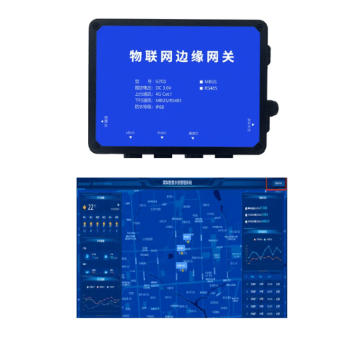
The NB IoT data logger battery powered outdoor terminal provides organizations with a solution which functions as a game changer for their outdoor and difficult to wire locations. Black Ant’s IoT Data Collection Terminal has an IP68 rating which enables it to function between -10°C and +55°C while using a battery that lasts for six years. The device can be installed in manholes substations or remote metering cabinets without needing power cables or requiring annual maintenance.
Implementation Steps for IoT Data Acquisition Terminals
Step 1 — Assess Your Field Devices and Protocol Requirements
Begin the process by conducting an inventory of all devices present at the site. Create a comprehensive list of all meters and sensors and controllers which you intend to monitor throughout the site. The following information must be documented for each device:
- The device’s manufacturer information and model number
- The device uses which communication protocol Modbus RTU and BACnet and M-Bus
- The device transmits data through which type of signal RS-485 and 4-20mA and pulse and digital IO
- The baud rate together with the register map must be documented when it is accessible
- The device requires specific power supply components to operate.
The inventory results determine both the necessary terminal type and required port quantity. A system needs two RS-485 ports and one M-Bus port and two analog inputs when your setup includes 20 Modbus heat meters and 10 M-Bus water meters and two 4-20mA pressure transmitters.
Step 2 — Select the Right Terminal for the Environment
Environment dictates enclosure rating and power supply. Use this guideline:
|
Location |
Recommended IP Rating |
Power Options |
|---|---|---|
|
Indoor mechanical room |
IP54 |
AC mains or DC adapter |
|
Covered outdoor cabinet |
IP65 |
AC mains with battery backup |
|
Exposed outdoor / buried |
IP68 |
Battery or solar hybrid |
Scalability also matters. Some terminals handle a few dozen data points. Others, like Black Ant’s centralized meter reader and concentrator-grade models, support up to 1,024 meter points per device. If you are planning future expansion, choose a terminal with headroom.
Step 3 — Physical Installation and Wiring
RS-485 wiring appears straightforward but any error leads to major issues. Follow these rules:
- Use shielded twisted-pair cable which meets RS-485 specifications.
- Devices should connect through a daisy-chain bus topology while star configurations should not be used.
- The bus system requires 120-ohm termination resistors to be installed at both its endpoints.
- Modbus RTU requires operators to maintain total cable length below 1,200 meters.
- To prevent ground loops, technicians should ground the cable shield at one end only.
All outdoor installations require surge protection for communication lines and power lines. IP68-rated enclosures must be sealed correctly after any wiring changes. One compromised gasket can destroy the terminal during the first heavy rain.
Step 4 — Configuration and Protocol Mapping
First, you should set up your terminal to communicate with your devices using a hardware setting. The principal parameters are:
- Modbus slave IDs, unique to each device in the network
- Baud rate, 9600 bps, or 19,200 bps for Modbus, and must match those of all connected nodes
- Register mapping, which registers to read and how much
- Data format, whether the raw values are scaled, and into which engineering units
- Uplink details, server address, established protocols (choose from MQTT, HTTP, or manufacturer’s proprietary), and the set data transmission interval
Present terminal devices facilitate over-the-air (OTA) updates for firmware. This could be very advantageous, especially for long-serving installations. Instead of going to each individual site, you are able to remotely update the software from your central management platform.
Step 5 — Commissioning and Validation
Commissioning proves the system works. Create a checklist:
- Verify real-time data appears on the dashboard for every device
- Compare terminal readings against local display values on meters
- Set alert thresholds and confirm notifications arrive correctly
- Disconnect the uplink temporarily and verify local buffering resumes upload after reconnection
- Document the as-built configuration, including device addresses, register maps, and cable routes
Only sign off when every data point is accurate and every alert path is tested.
Real-World Applications and Use Cases
District Heating Substations
A facilities team in Northern China manages 40 district heating substations. Before installing IoT terminals, operators read ultrasonic heat meters manually once per month. Leaks went undetected for days. Flow imbalances wasted energy at the end of the loop.
The Black Ant IoT data collection terminal installation at every substation enables the team to monitor real-time data flow together with temperature and pressure measurements from all system nodes. The terminals collect data through RS-485 and M-Bus from heat meters and pressure transmitters and temperature sensors. The system generates alerts within seconds after detecting a pressure drop. The system achieved better flow balancing results. The heating energy expenses reduced by 20 to 30 percent during the initial heating season.
Commercial HVAC Retrofits
It is not uncommon for numerous connected HVAC systems using mixed technologies and equipment from decades-old types to serve mixed-use commercial buildings. While a BACnet is spoken by the BMS, Modbus is the lingua franca among fan coil units, while M-Bus is the linguistic model for all utility meters. Pull everything out and you will have an expensive replacement; keep it, in the meantime your view on energy will be fractured.
An IoT data acquisition terminal bridges this gap. It connects to legacy wireless HVAC control units and fan coil control valves via Modbus, reads the meters via M-Bus, and translates everything into BACnet for the existing BMS. The building gets modern real-time monitoring without a rip-and-replace project.
Smart City Infrastructure
Smart cities need data from assets that are scattered, exposed, and hard to power. Think of smart manhole covers with tilt and gas sensors, environmental monitoring stations measuring PM2.5 and noise, and remote water level sensors in municipal drains.
The making of an IP68 edge data acquisition IoT gateway empowered by battery is here. He will wake on programmed intervals, read the sensors, perform data pre-processing at the edge, and deliver the same, over NB-IoT or LoRaWAN. Thanks to a six-year battery life span and no need for wiring, these can be deployed in great quantities across the city without adding any more staff for maintenance.
Choosing a Reliable Terminal Partner
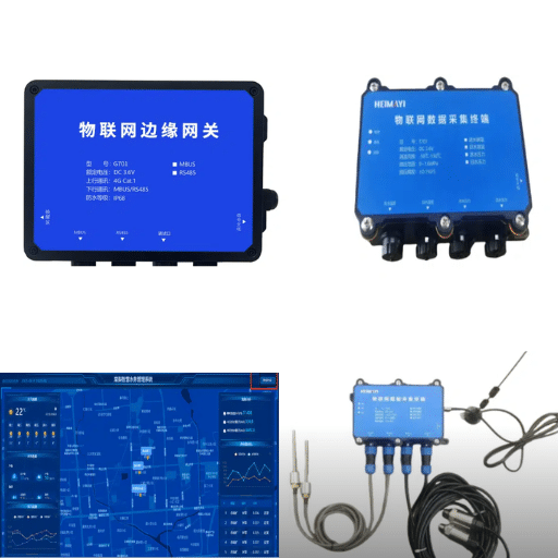
Not all terminals are equal, and not all suppliers can support you through deployment. When you view all of the suppliers/vendors that are out there, look at the following features:
- Acceptor of multiple protocols — Modbus, BACnet, M-Bus, MQTT, and HTTP, all standard on that device
- Acceptable environmental standards — IP54 for indoor, then IP67/IP68 for outdoor use
- Accreditations — CE, RoHS, ISO 9001; required for international projects
- Options for OEM or ODM — custom firmware, register maps, enclosure branding for system integrators
- Support for commissioning — Forms, from product manuals to field-engineered applications, combined with customer services
Unlike its competitors, Black Ant opts to deal with the design and production of its own Dataloggers starting with all aspects from its plants. Being ISO 9001 certified will keep our products being produced in volumes on an equal consistent quality ground. This is served toward flexible offerings with OEM/ODM arrangements, ranging from custom Modbus register maps to common enclosure brands. The engineering department partners with systems integrators to take concepts from start to commissioning— because we share in this success of yours on any site.
Conclusion
The IoT data acquisition terminals would close the loop between the field devices and real-time decision-making. They transformed autonomous meters, sensors, and controllers into a single system of monitoring. The edge terminals process the data locally to achieve cycles of milliseconds with the highest responsiveness. These terminals also have the advantage of making retrofit projects a financially viable prospect, using them for bridge legacy protocols to modern platforms.
While planning for deployment, you must begin with a well-detailed inventory of devices. Choose a rugged and edge-ready terminal that fits well within your environment and protocol mix. Plan the cable layouts accordingly. And be sure to validate every data point at commissioning before giving them over.
For facility managers and systems integrators looking to build smarter, more efficient infrastructure, the right IoT data acquisition terminal is not just a piece of hardware. It is the foundation of your building energy management system. Contact our application engineers for a free project consultation on your IoT data acquisition terminal deployment.