4–20 mA Pressure Transmitter Loop Power Budget: Supply Voltage, Cable Drop and Input Burden
A 4-20 mA loop power budget checks whether enough voltage remains at a pressure transmitter after the cable, receiving input and series accessories take their share. Calculate it at the lowest available supply voltage and every required operating condition, including the highest required output current.
A transmitter can have enough voltage at low current but insufficient voltage near full scale. WIKA’s PLC integration explanation describes this problem when a loop-powered indicator is added. Checking the voltage allocation helps you assess the loop before replacing a sensor or changing the supply.
This worksheet covers a two-wire DC series loop. For the signal principle, see our 4–20 mA pressure transmitter fundamentals.
Key takeaways
- Use the supply’s documented lower voltage bound, rather than its nominal label alone.
- Include input burden, both cable conductors and every series accessory, counting each load once.
- Use the selected transmitter’s load curve and configured current requirements; 20 mA is not automatically the most demanding point.
- Check receiver current range separately from voltage margin. A positive voltage calculation establishes only one part of compatibility.
1. Collect the inputs for your loop power budget
Confirm which device supplies the loop
Identify the actual source of loop power. A passive current input measures the signal while another device supplies the loop; a powered input may itself provide the transmitter supply. Check the receiving module’s documentation and the pressure transmitter wiring guide before assigning voltage values.
If the input powers the transmitter, use its documented available voltage under the relevant load conditions. Do not assume that the controller’s nominal supply appears unchanged at the field terminals. If an interface divides the signal path into separate powered loops, calculate each loop separately.
Fill in the specification worksheet
Record the document revision and selected option beside every value. NI’s current-loop design guide explains the underlying accounting: the supply must cover the transmitter’s voltage requirement and the drops elsewhere in the loop.
| Input | Record this value | Document and condition to check |
|---|---|---|
| Loop source | Minimum available voltage, V | Supply tolerance, loading and specified operating conditions; powered-input output limits where applicable |
| Transmitter | Required terminal voltage, V, and permitted load curve | Exact model, output option and applicable operating conditions |
| Required current | Highest required output current, A | Configured measurement, overrange and high-alarm requirements, including applicable tolerances |
| Receiving input | Burden in Ω or voltage drop in V | Exact input module, selected channel mode and stated limits |
| Cable and connections | Total outgoing-plus-return resistance, Ω | Conductor resistance, installed length, temperature conditions and connection allowances |
| Series accessories | Each device’s specified voltage drop, V, or resistance, Ω | Display/interface model, current, operating mode and other stated conditions |
An unknown value is a request for documentation. Avoid filling a missing field with a familiar 24 V supply, 250 Ω input or another transmitter’s minimum voltage.
2. Calculate transmitter terminal voltage and margin
Separate resistance from accessory voltage drop
For the defined series loop, group resistive loads together. Keep electronic accessories with a specified voltage requirement in a separate sum. The following equations are a steady-state worksheet derived from voltage accounting and Ohm’s law; the selected manufacturer’s limits still apply.
R_series = R_input + R_cable_round_trip + R_other_resistive

V_tx_available(I) = V_supply_min - I × R_series - sum(V_accessory(I))

M(I) = V_tx_available(I) - V_tx_required(I)
Here, I is loop current in amperes, resistance is in ohms and all voltages are in volts. V_tx_available is the voltage left across the transmitter terminals; V_tx_required is its documented requirement for that condition. M is the remaining voltage margin.
Convert milliamperes to amperes before multiplying: 20 mA equals 0.020 A. For a specified or hypothetical 250 Ω input, its drop at that current is 0.020 × 250 = 5.00 V. That is the input’s drop alone, rather than the voltage required by the whole loop.
Count each burden once. If an accessory’s documented voltage drop already includes its internal resistance, adding that resistance again would overstate the burden. For nonlinear electronics, use the specified drop at the relevant currents and modes rather than assuming a constant resistance.
Include both cable conductors
When the cable specification gives resistance per conductor per unit length, two equal conductors give:
R_cable_round_trip = 2 × L_one_way × r_per_conductor_per_unit_length
Use matching length units. If the data already states resistance for a conductor pair or complete loop, do not double it again. For unequal conductors, add their individual resistances.
NI’s guide explicitly includes the outgoing and return paths in its cable calculation. For your worksheet, use applicable resistance limits and temperature conditions from the actual cable documentation. A nominal room-temperature value does not establish the maximum installed resistance.
Calculate the allowable resistance or required supply
For a specified design current and accessory drop at that current, rearrange the same equation:
R_series_allowable =
 (V_supply_min - V_tx_required - sum(V_accessory)) / I_design

V_supply_required =
 V_tx_required + I_design × R_series + sum(V_accessory)
The resistance allowance covers all loads assigned to R_series, including the input and cable. If the numerator is negative, the assumed source cannot cover the transmitter and accessory voltage requirements even before adding resistive losses.
These expressions do not prescribe a reserve percentage. If your project requires extra voltage reserve, record that requirement and subtract it once when calculating the load allowance.
3. Check supply limits, output current and the model’s load curve
Use the lowest documented source voltage
A nominal voltage is a label for normal operation, not necessarily the minimum available voltage. Use the lower bound established by the relevant source specification and load conditions. Account for any supply-feed loss between that reference point and the loop, without counting it again as signal-cable resistance.
Also check the opposite limit: the highest voltage the equipment could experience must remain within its permitted ratings. NI’s guide distinguishes minimum operating voltage from maximum permitted voltage; increasing the supply is therefore a design change that needs both checks.
Choose current from the actual output requirements
Check the highest current your application requires the transmitter to deliver. This can include an output above 20 mA for overrange or a configured high alarm. Use the model’s documentation and applicable tolerances rather than adopting 22 mA as a universal value.
The manufacturer may publish a load equation that already embeds its own current and voltage assumptions. For example, the WIKA S-20 data sheet PE 81.61, revision 02/2026, gives a two-wire load limit based on (supply voltage − 7.5 V) / 0.023 A. Its 1,000 Hz option footnote instead uses an 11.5 V offset and different supply limits. This is a model-specific example of why options matter, not a Black Ant specification. See the output and supply tables on printed pages 7–8 of the S-20 data sheet.
Apply the selected model’s published load curve alongside the worksheet. Do not replace its denominator or offset simply because the normal measurement range ends at 20 mA. Check documented startup or other operating-mode constraints separately where they differ.
Keep input range separate from input burden
Input burden determines how much voltage the receiver consumes. Input range determines which currents it can measure within its stated specifications. Neither value establishes the other.
Before accepting an overrange or alarm-current requirement, compare it with the receiving module’s documented range and guarantees. A loop can have adequate transmitter terminal voltage while the receiver cannot measure the required current.
4. Worked example: enough voltage at 20 mA, insufficient at 22 mA
Illustrative scenario: Every component value below is an assumption for teaching. These are not Black Ant product specifications, a customer installation or a recommended component combination.
| Assumed input | Value |
|---|---|
| Nominal supply | 24 V |
| Assumed lower supply bound | 10% below nominal, giving 21.6 V |
| Transmitter terminal-voltage requirement | 12 V over the illustrated conditions |
| Receiving input resistance | 250 Ω |
| Total outgoing-plus-return cable resistance | 40 Ω |
| Series accessory drop | Constant 3.5 V over the illustrated conditions |
| Highest required output current | 22 mA |
The resistive total is 250 + 40 = 290 Ω. At the assumed 22 mA requirement, use I = 0.022 A:
Resistive drop = 0.022 × 290 = 6.38 V
Transmitter terminal voltage = 21.60 - 6.38 - 3.50 = 11.72 V
Margin = 11.72 - 12.00 = -0.28 V
Repeating the same calculation at three currents shows why a low-current check can miss the shortfall:
| Required current | Drop across 290 Ω | Accessory drop | Calculated transmitter voltage | Margin above 12 V |
|---|---|---|---|---|
| 4 mA | 1.16 V | 3.50 V | 16.94 V | +4.94 V |
| 20 mA | 5.80 V | 3.50 V | 12.30 V | +0.30 V |
| 22 mA | 6.38 V | 3.50 V | 11.72 V | −0.28 V |
At 20 mA, the simplified inequality is met with 0.30 V remaining. At the required 22 mA, it is short by 0.28 V. The 22 mA row evaluates a demanded operating point; it does not claim that a voltage-starved transmitter can actually sustain that current.
Under these assumptions, the minimum source voltage needed at 22 mA is 12 + 6.38 + 3.50 = 21.88 V. The assumed available 21.6 V is insufficient.
Alternatively, the total resistance allowance is (21.6 − 12 − 3.5) / 0.022, or approximately 277.27 Ω. The assumed 290 Ω exceeds that allowance. Removing the assumed accessory from the arithmetic would leave 3.22 V of margin at 22 mA.
Those comparisons show which terms affect the result. Any real change still needs actual component limits, current-range checks and project requirements. A low reading near full scale also has other possible causes, so this pattern alone does not diagnose a power problem.
5. Recalculate after adding a display or interface
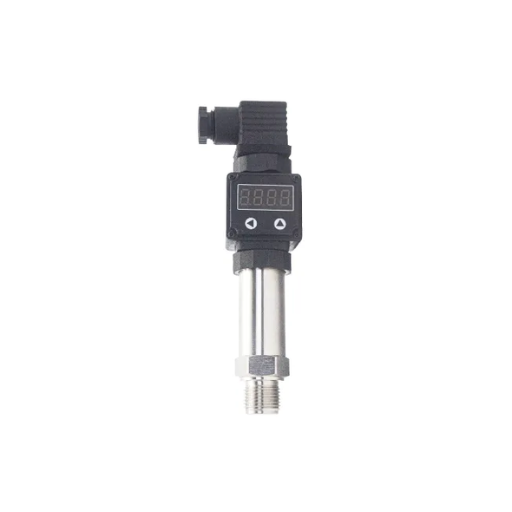
A series loop-powered display obtains energy from the loop and needs voltage across its terminals. WIKA’s PLC integration article explains why adding one can prevent a transmitter from reaching the top of its output range when the source cannot cover both devices’ requirements.
For the actual accessory, use the drop specified for its selected mode and operating conditions. Check whether lighting or another enabled feature changes that requirement. Do not transfer a voltage-drop figure from an unrelated display.
If an interface creates separate input and output loops, draw those boundaries before calculating. Each powered segment has its own source and burdens. Adding every device across both segments into one series sum would misrepresent the circuit.
Revisit the worksheet whenever the input module, cable route, transmitter option or series accessory changes. Keep the calculation with the component documents so the next engineer can see which configuration it describes.
6. Prepare a specification checklist before ordering or commissioning
For a component comparison or supplier inquiry, gather:
- The exact transmitter model, output option, load curve and permitted supply range.
- Required measurement, overrange and configured alarm currents, with applicable tolerances.
- The loop source’s minimum available voltage and maximum possible voltage under the relevant conditions.
- The receiver model, active/passive arrangement, input burden and measurable current range.
- One-way cable length, conductor-resistance convention, temperature conditions and connection allowances.
- Every series accessory and its voltage drop or resistance in the intended mode.
For a Black Ant selection, start with our pressure transmitter product information and request the electrical data sheet for the configuration you are considering. Compare that documentation with your receiving module and cable data before confirming the selection.
During commissioning, qualified personnel should verify relevant terminal voltage and loop current through the equipment’s approved procedures. The paper budget does not replace the model’s instructions or establish safety, grounding, electromagnetic compatibility or protocol compatibility. Shared supplies also need sufficient current capacity for all connected loops under their required conditions.
If the calculated voltage margin is adequate but the reading remains wrong, continue with pressure transmitter troubleshooting. Record the operating current and configuration with the voltage observation so they can be compared with the worksheet.
7. Questions about loop supply voltage
Is 24 V always enough for a pressure transmitter loop?
No. Compare the lowest available source voltage with the selected transmitter’s requirement, cable drop, receiver burden and accessory drops. The worked example starts with a nominal 24 V supply but fails its assumed 22 mA requirement at the lower supply bound.
Does every 4–20 mA input have a 250 Ω burden?
No universal burden should be assumed. Use the exact input module’s specification and selected mode. The 250 Ω value in this article is explicitly hypothetical.
Does cable resistance include the return conductor?
That depends on the data convention. A per-conductor figure needs the outgoing and return resistances added together. A complete-loop figure already includes both paths.
Can I increase the supply voltage to fix a shortfall?
Only if the revised supply conditions remain within every affected device’s permitted limits and the manufacturer’s instructions. Recheck both the minimum available voltage and maximum possible voltage, then reassess the complete loop rather than treating a positive margin as approval.