HVAC Energy Saving Fan Coil Valve Control: An Engineer’s Guide to Efficient Terminal Unit Regulation
A 12-story office building in Bangkok was spending more on cooling each year even though occupancy had barely changed. The facility manager, Supachai, suspected the fan coil units were the problem. Hundreds of valves were hunting between open and closed, and coils were running hot and cold simultaneously. Pumps were working overtime to push water through bypass circuits that should not have been active.
After a focused retrofit of the fan coil control valves and room temperature controllers, the building cut its HVAC energy use by 24% in the first year. The fix was not a new chiller or a full BMS replacement. It was better control at the terminal units.
That is the case for taking HVAC energy saving fan coil valve control seriously. Fan coil units are the most common terminal units in commercial buildings, yet their valves are often oversized, poorly commissioned, or left open when spaces are unoccupied. Every one of those problems converts directly into wasted heating or cooling energy, higher pump loads, and tenant comfort complaints.
In this guide, you’ll learn how the right fan coil control valve strategy cuts energy use, improves comfort, and extends equipment life. We’ll cover 2-way versus 3-way valves, normally open versus normally closed selection, Kvs and Cv sizing, energy-saving control strategies, protocol integration, commissioning, and ROI. Whether you’re a facility manager, an HVAC integrator, or a procurement professional, this article will help you make technically sound, commercially smart decisions.
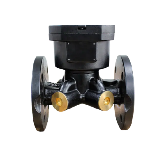
Want to see the hardware behind these strategies? Explore Black Ant’s fan coil control valve range for DN15/DN20/DN25 2-way and 3-way options with RS485, BACnet, and Modbus support.
How HVAC Energy Saving Fan Coil Valve Control Affects Building Energy Use

Why Valve Control Is the Key to Fan Coil Efficiency
Fan coil units regulate room temperature by adjusting hot or chilled water flow through the coil. The valve is the actuator of that decision. When the thermostat calls for more cooling, the valve opens. When the setpoint is reached, it modulates or closes.
If the valve is correctly sized and controlled, the coil delivers exactly the capacity the room needs, no more, no less.
Poor valve control breaks that balance. Oversized valves throttle at very low strokes, which reduces authority and causes hunting. Undersized valves cannot deliver enough capacity at peak load. Leaky valves let water through when they should be closed, keeping the coil active and wasting energy.
Each of these problems is measurable on the utility bill.
The Energy Waste Hidden in Terminal Units
The most common source of waste is not the chiller or boiler. It’s what happens at the terminal unit after the conditioned water has already been generated.
- Overheating and overcooling occur when valves don’t close fully or respond too slowly. The space temperature overshoots the setpoint, and the control loop overcorrects.
- Pump energy penalties are common in constant-flow systems where 3-way bypass valves keep the same volume of water moving even when the coil doesn’t need it. Variable-flow systems with correctly selected 2-way valves reduce this load.
- Simultaneous heating and cooling in 4-pipe systems can waste 15–25% of HVAC energy when valves on both coils are active at the same time or when deadbands are too narrow.
According to the U.S. Department of Energy, HVAC systems account for roughly 40% of commercial building energy use in the United States. The International Energy Agency reports that buildings globally consume about 30% of final energy. Because fan coil units are so widespread, even small improvements in terminal control add up to large savings.
How Does a Fan Coil Control Valve Save Energy?
A fan coil control valve saves energy by matching coil capacity to actual room load in real time. A modulating valve with good authority can hold the space within ±0.5°C of setpoint, eliminating the temperature swings that cause overcooling and reheating. When paired with setback scheduling and occupancy-based setpoints, the valve closes or throttles during unoccupied hours, reducing both coil and pump energy.
2-Way vs 3-Way Valve Fan Coil Unit Comparison
Before comparing the two valve types, it helps to understand the full selection process end to end. Our Fan Coil Control Valve: The Complete Engineer’s Selection and Sizing Guide walks through valve types, sizing, and specification in detail if you want the complete picture.
Two-Way Valves for Variable Flow Systems
A 2-way valve has one inlet and one outlet. It opens to allow flow through the coil and closes to stop it. In a variable-flow system, when the valve closes, the flow rate through that branch drops. The system pump, typically a variable-speed drive, responds by reducing speed, which saves pump energy.
2-way valves are the right choice for modern hydronic designs because they align with variable-flow logic. They are also the lower-cost option and simpler to commission.
Three-Way Valves for Constant Flow Systems
A 3-way valve has three ports and either mixes or diverts flow. In a diverting configuration, water is sent either through the coil or through a bypass. The total system flow stays roughly constant. This was the default design for older constant-volume systems with fixed-speed pumps.
3-way valves make sense in retrofits where the existing pump cannot be converted to variable speed, or in systems where constant flow must be preserved to protect other equipment. They are also used in some 4-pipe changeover designs.
Which Valve Type Saves More Energy?
The answer depends on the rest of the system. In a new or fully retrofitted building with variable-speed pumps and pressure-independent loops, 2-way valves save more energy because they reduce pump power. In a legacy constant-flow system, a 3-way valve may be the only practical choice without major infrastructure work, though the energy savings will be smaller.
| Feature | 2-Way Fan Coil Valve | 3-Way Fan Coil Valve |
|---|---|---|
| Ports | 2 (inlet and outlet) | 3 (inlet, outlet, bypass) |
| Flow behavior | Variable flow when closing | Constant total flow via bypass |
| Best system | Variable-speed pumping | Constant-speed pumping |
| Energy savings | Higher in modern systems | Lower; protects legacy pump design |
| First cost | Lower | Higher |
| Common application | New FCU installations, retrofits with VFD pumps | Constant-flow legacy systems, changeover designs |
Need help choosing for your project? Black Ant’s electric control valve range includes 2-way and 3-way configurations in DN15, DN20, and DN25 with AC220V and DC24V actuators.
Normally Open vs. Normally Closed Selection

Fail-Safe Position and Occupant Safety
Electric control valves are specified as either normally open (NO) or normally closed (NC). The “normal” position is what the valve does when power is removed.
- Normally open valves open on power loss. They are common in heating-dominated climates where freezing protection is the priority.
- Normally closed valves close on power loss. They are used in cooling-dominated applications or where leakage protection matters.
How Fail Position Affects Energy Use
The wrong fail position can waste energy. In an office building with heavy internal loads, an NO cooling valve that opens on power loss will continue to overcool the space during outages or control failures. Conversely, an NC heating valve in a cold climate may allow pipes to freeze. Match the fail position to the dominant load and the safety requirement, not just the lowest catalogue price.
Sizing Fan Coil Control Valves with Kvs and Cv
Why Correct Sizing Matters
Valve sizing is where many energy-saving opportunities are won or lost. An oversized valve operates at a small percentage of stroke, which gives it poor resolution and authority. It will hunt, causing temperature oscillation and wear. An undersized valve starves the coil at peak load, forcing the fan and pump to compensate.
Aim for a valve authority between 0.5 and 1.0. Authority is the ratio of pressure drop across the fully open valve to the total pressure drop across the branch. At 0.5 or higher, the valve has enough influence over the flow to modulate smoothly.
Kvs and Cv Flow Coefficients Explained
- Kvs is the metric flow coefficient: the flow rate in cubic metres per hour (m³/h) of water at 1 bar pressure drop across the fully open valve.
- Cv is the imperial equivalent: the flow rate in US gallons per minute (GPM) of water at 1 psi pressure drop.
The conversion is straightforward: Cv ≈ Kvs × 1.156.
To size a valve for a fan coil unit, calculate the design flow rate from the coil load and the temperature difference between supply and return water. Then select a Kvs that gives a reasonable pressure drop at design flow, typically 3–10 kPa for small fan coil valves.
Fan Coil Valve Kvs Sizing Table DN15 DN20 DN25
| Valve size (DN) | Typical Kvs range | Common coil load | Pipe connection |
|---|---|---|---|
| DN15 | 0.25–1.6 | 1.5–5 kW | G 1/2″ threaded |
| DN20 | 1.0–4.0 | 4–12 kW | G 3/4″ threaded |
| DN25 | 2.5–6.3 | 10–20 kW | G 1″ threaded |
This table is a starting point. Always confirm the actual coil duty, design flow, and available differential pressure before specifying. Black Ant’s fan coil control valves cover DN15 through DN25 with Kvs ratings matched to common commercial fan coil unit loads.
HVAC Energy Saving Fan Coil Valve Control Strategies

On-Off vs. Modulating Control
On-off control is simple and inexpensive. The valve is either fully open or fully closed. The downside is wider temperature swings and more cycling, which can reduce comfort and equipment life.
Modulating control varies the valve position proportionally to the deviation from setpoint. The result is smoother operation, tighter temperature control, and deeper energy savings.
Studies of modulating control valves in commercial HVAC applications typically report energy savings of 15–25% compared with on-off control, primarily because modulating valves avoid the overshoot and reheating penalty.
Room Temperature Controller Integration
The valve cannot save energy on its own. It needs a controller that tells it when to open and close. A good room temperature controller does more than maintain setpoint:
- Setback scheduling raises cooling setpoints and lowers heating setpoints during unoccupied hours.
- Deadband settings prevent both heating and cooling valves from opening at the same time in 4-pipe systems.
- Setpoint limiting stops occupants from driving temperatures to extremes.
If you’re weighing controller features, wiring options, and compatibility, our Room Temperature Controller for HVAC Fan Coil Systems: An Engineer’s Selection Guide breaks down how to choose the right controller for 2-pipe and 4-pipe applications.
Black Ant’s T6 room temperature controller supports LoRa and 4G wireless communication, making it suitable for retrofit projects where running new BMS wiring is not practical. It is compatible with 2-pipe and 4-pipe fan coil units and includes smart scheduling logic.
Pressure-Independent Control Valves (PICVs)
A pressure-independent control valve, or PICV, combines a control valve and a pressure regulator in one body. It maintains the design flow rate to the coil regardless of changes in system differential pressure. This matters because system pressure changes constantly as other valves open and close.
PICVs reduce commissioning time and protect against over-flow, which is a common cause of energy waste in variable-flow systems. In buildings where other branches close, a standard valve might see a higher differential pressure and overfeed the coil; a PICV will not. The trade-off is a higher first cost, which is why PICVs are best applied on projects where commissioning precision and long-term energy savings justify the investment.
For a deeper look at how PICVs work, when to specify them, and how to size them correctly, see our Pressure Independent Control Valve Fan Coil: Engineer’s Guide.
Zone Control and Occupancy-Based Setpoints
Grouping fan coil units into zones and applying occupancy-based control multiplies the savings. When a zone is unoccupied, valves close and setpoints drift. When occupancy is detected, the controller returns to comfort settings. The same logic applies to daylight harvesting and demand-controlled ventilation integration. Black Ant’s control valves and controllers support the open protocols, Modbus RTU, BACnet MS/TP, and RS485, that make zone-level integration possible.
BACnet Modbus HVAC Control Valve Protocol Integration
Modbus RTU for Fan Coil Valve Control
Modbus RTU over RS485 remains the default protocol for cost-effective fan coil valve integration. It is simple, widely supported, and easy to troubleshoot. The Modbus Organization maintains the open specification, and most BMS platforms, PLCs, and third-party controllers can read Modbus registers natively.
For a fan coil valve retrofit, the typical setup is a daisy-chain RS485 bus with each valve actuator addressed individually. The controller polls each actuator for position and status and sends setpoint or valve commands. Baud rates of 9,600 or 19,200 are common.
BACnet MS/TP and BACnet IP
BACnet is often specified in commercial and institutional projects, especially when the BMS platform is Honeywell, Siemens, Johnson Controls, or Schneider. BACnet MS/TP runs over RS485, while BACnet IP runs over Ethernet. Black Ant fan coil control valves support BACnet MS/TP, allowing direct integration without protocol gateways. For larger sites, a centralized building energy management system aggregates these protocol streams into a single operations dashboard.
Room Temperature Controller HVAC Wireless: LoRa and 4G Options
Not every building has a BMS, and not every retrofit budget allows for new cabling. Wireless room temperature controllers with LoRa or 4G communication solve this problem. They can be installed in under an hour and provide remote monitoring and setback control without a central BMS. For facility managers overseeing multiple buildings, this is often the fastest path to energy savings.
Commissioning and Maintenance for Lasting Savings

Commissioning the Control Loop
Commissioning is where theoretical savings become real savings. A poorly commissioned valve will waste energy regardless of how well it was sized. Following ASHRAE commissioning guidelines helps ensure the basics are checked consistently. The core steps are:
- Confirm the actuator direction matches the controller signal.
- Verify the valve closes fully against the coil pressure.
- Set the stroke limits to match the controller output range.
- Tune the control loop for stable response without hunting.
- Document the final Kvs, authority, and setpoints for future reference.
Common Commissioning Errors
- Reversed actuator direction causes the valve to open when the controller wants it to close.
- Incorrect Kvs selection leads to hunting or insufficient capacity.
- Bypass loops left open defeat variable-flow savings by keeping constant flow.
- No deadband in 4-pipe systems allows simultaneous heating and cooling.
Maintenance Best Practices
Annual maintenance should include a stroke test, actuator torque check, seal inspection, and controller schedule review. A valve that takes 10 seconds longer to close than it should is already wasting energy. Catching that early prevents months of unnecessary utility spend.
ROI: Quantifying Fan Coil Valve Energy Savings
Typical Energy Reduction Potential
Documented HVAC control retrofits using precise fan coil valve control and room temperature controllers typically achieve 20–30% reductions in HVAC energy consumption. The split usually includes:
- 10–15% from reduced coil energy due to tighter temperature control and setback.
- 5–10% from reduced pump energy in variable-flow systems.
- 5–10% from reduced reheating and simultaneous heating and cooling.
Simple ROI Calculation Framework
Consider a 200-zone office building with an annual HVAC energy cost of $80,000. A fan coil valve and controller retrofit that saves 25% cuts that to $60,000. That is $20,000 saved per year.
If the retrofit costs $60,000, the simple payback is 3 years. Over a 10-year equipment life, the net savings are $140,000 before maintenance benefits.
Non-Energy Benefits
The savings are not only on the utility bill. Better valve control also delivers:
- Fewer hot and cold spot complaints from occupants.
- Longer valve and coil life from reduced cycling and hunting.
- Easier compliance with building energy codes and ESG reporting requirements.
- Lower maintenance callouts because the system runs closer to design intent.
A facilities director in Dubai, Fatima, saw this firsthand. After upgrading the fan coil valves and adding wireless room controllers with setback scheduling, her team’s monthly HVAC-related tenant complaints dropped by 60%. The energy savings paid for the hardware in under three years, but the reduction in reactive maintenance was what convinced her to roll the same package out to the rest of the portfolio.
OEM and Customization for Integrators and Distributors

Private-Label Fan Coil Valves and Controllers
For integrators and distributors, sourcing a reliable control valve platform is as important as the technical specification. Black Ant manufactures fan coil control valves, room temperature controllers, and data acquisition hardware in-house, with ISO 9001-certified processes. OEM and ODM orders can include:
- Custom actuator voltages and valve body materials.
- Private-label branding and packaging.
- Custom firmware and Modbus register mapping.
- Specific connection threads and pressure ratings.
MOQ and Lead Time Considerations
Standard catalogue products typically ship within 3–6 weeks. OEM programs involve first-article inspection and tooling confirmation, which extends the initial lead time but creates a repeatable supply path for repeat orders. For project-based procurement, it is worth planning the first-article phase into the project schedule.
Conclusion
HVAC energy saving fan coil valve control is one of the most cost-effective ways to reduce building energy use without replacing major plant equipment. The key decisions are:
- Choose 2-way valves for variable-flow systems and 3-way valves where constant flow must be preserved.
- Size the valve correctly using Kvs or Cv to maintain authority and avoid hunting.
- Select normally open or normally closed based on the dominant load and safety requirement.
- Use modulating control and room temperature controllers with setback scheduling.
- Commission the loop properly; savings depend on correct installation and tuning.
- Integrate using open protocols like Modbus RTU or BACnet for BMS compatibility.
- Calculate ROI using energy baselines, retrofit costs, and documented savings percentages.
As buildings face tighter energy codes and rising utility costs, the margin for inefficient terminal control is shrinking. The good news is that the hardware to fix it is proven, certified, and available at scale. Whether you are retrofitting one building or specifying hardware for a portfolio, the right fan coil control valve strategy pays back in measured energy savings and measurable comfort.
Ready to improve your building’s fan coil control? Explore Black Ant’s fan coil control valve range and wireless room temperature controllers, or contact our engineering team for a project-specific valve sizing recommendation.