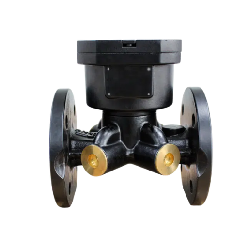
Fan Coil Valve Actuator Types: How to Choose the Right Actuator for Your FCU
A failed fan coil valve actuator is the kind of problem that shows up as a guest complaint long before it triggers a maintenance ticket. The room is too hot. The room is too cold. The valve is stuck open and the coil is wasting chilled water all night. The actuator was the cheapest part of the terminal unit, yet it controls comfort, energy use, and maintenance frequency for the next ten years.
If you are specifying, commissioning, or replacing fan coil valve actuators, the market gives you more choices than the catalog makes clear. Thermal or motorized. On/off or modulating. Normally open or normally closed. Spring return or non-spring return. Each fan coil valve actuator type solves a specific control problem, and choosing the wrong one means hunting valves, noise complaints, and higher energy bills. This guide compares the main fan coil valve actuator types, matches them to real FCU applications, and shows how to select the right actuator for 2-pipe, 4-pipe, and BMS-integrated systems.
Want to see the valves these actuators mount to? Explore the Black Ant fan coil control valve range, DN15/DN20/DN25, 2-way and 3-way, with AC220V and DC24V actuator options.
What Is a Fan Coil Valve Actuator?

A fan coil valve actuator is the powered device that moves the stem of a fan coil unit water valve. It receives a control signal from a thermostat, room temperature controller, or building management system, and opens or closes the valve to regulate hot or chilled water flow through the coil. Without the actuator, the valve is a static fitting. With the right actuator, the FCU becomes a precision zone temperature control device.
The actuator typically consists of a drive element, either a wax thermal element or an electric motor, a gear train or stroke mechanism, limit switches or position feedback, and an electrical interface for power and control signals. Some include a manual override for commissioning. Others include a return spring that drives the valve to a safe position when power is lost.
Fan coil valve actuator types are usually classified by two things: the drive technology and the control logic. The drive technology is either thermal or electromechanical. The control logic is on/off, 3-point floating, or proportional modulating. Combine those two dimensions and you get the practical range of actuators found in FCU projects today.
Main Fan Coil Valve Actuator Types
Motorized Electromechanical Actuators
Motorized actuators use a small electric motor to drive the valve stem. They are the most common fan coil valve actuator type in commercial buildings because they offer fast response, high torque, and compatibility with a wide range of control signals.
A typical FCU motorized actuator runs on AC220V or DC24V and moves from fully closed to fully open in 5–20 seconds. The motor drives a gear reduction train that converts rotary motion into the linear stroke needed by a globe or zone valve body. Limit switches stop the motor at the end positions, and some models add a potentiometer or 0–10V feedback signal for position indication.
Motorized actuators are the right choice when the system needs fast response, precise modulation, or integration with a BMS. They can also deliver higher close-off force than thermal actuators, which matters in high-pressure hydronic systems. The trade-off is slightly higher power consumption and a small amount of motor noise during operation.
Black Ant’s fan coil control valves use motorized actuators with a 2–5 second response time and ±0.5°C zone accuracy. That speed matters because a slow actuator lets room temperature drift past the setpoint before the valve can react.
Thermal Electrothermal Actuators
Thermal actuators, sometimes called electrothermal or wax motor actuators, use an electric heating element to expand a wax pellet or thermal element. The expansion pushes a piston that moves the valve stem. When power is removed, the element cools and contracts, allowing a spring to return the valve to its resting position.
The defining characteristic of a thermal actuator is its slow stroke time. A full open or close cycle typically takes 1–3 minutes. That sounds like a disadvantage, but in many FCU applications it is exactly what you want. The slow movement eliminates water hammer and produces virtually silent operation. Hotels, residential buildings, and healthcare facilities often specify thermal actuators for terminal units because guests and patients do not hear them cycle.
Thermal actuators also draw very little power, usually 1–3 W, because they only need enough energy to maintain the thermal element at the expansion temperature. The downside is poor suitability for modulating control. Thermal actuators are inherently on/off devices, and their slow response makes them a poor match for systems that need continuous flow adjustment.
Spring-Return Fail-Safe Actuators
Spring-return actuators can be either motorized or thermal, but the category is worth separating because the fail-safe behavior changes the application. A spring-return actuator stores mechanical energy in a spring during normal operation. When power is removed, the spring drives the valve to a predetermined safe position, normally closed for most fan coil cooling applications, or normally open where freeze protection or heating priority matters.
Spring-return motorized actuators are common in life-safety and critical-process applications. In a fan coil system, the most common reason to specify spring return is freeze protection. If a heating-only FCU loses power in cold weather, a normally open spring-return actuator keeps hot water flowing through the coil and reduces the risk of pipe freezing.
The trade-off for spring return is higher actuator cost, larger physical size, and sometimes shorter service life because the spring is loaded continuously. For standard commercial fan coil units, non-spring-return actuators are the default unless the specification explicitly requires fail-safe behavior.
Thermal Actuator vs Motorized Actuator for Fan Coil Units

The thermal vs motorized decision is the first fork in the road for most FCU projects. The table below summarizes the practical differences.
| Feature | Thermal Actuator | Motorized Actuator |
|---|---|---|
| Stroke speed | 1–3 minutes full stroke | 5–20 seconds full stroke |
| Power consumption | 1–3 W while holding | 5–6.5 W while running |
| Noise level | Virtually silent | Low motor/gear noise |
| Control signals | On/off, sometimes PWM | On/off, 3-point, 0–10V, 4–20mA, Modbus/BACnet |
| Modulating control | Poor, slow response | Excellent, precise positioning |
| Best applications | Hotels, residential, quiet zones | Commercial buildings, BMS-integrated systems |
| Maintenance | Fewer moving parts | More complex, but serviceable |
Consider the case of a 120-room hotel in Bangkok that replaced its aging motorized FCU actuators with thermal units in the guest rooms. The engineering team wanted to eliminate the clicking sound that woke guests when valves cycled at night. Thermal actuators solved the noise problem and reduced power draw at the terminal unit. However, the thermal units were a poor fit for the banquet hall FCUs, where rapid load changes required faster response. The hotel ended up with thermal actuators in guest rooms and motorized actuators in public spaces, a split that matched the application rather than standardizing on one type.
Need help matching the actuator to your FCU control signal? Read our guide on BACnet and Modbus integration for HVAC control valves before you finalize the specification.
Control Signal Types Explained
The actuator type is only half the decision. The control signal determines how the actuator receives commands from the thermostat or BMS.
On/Off Two-Position Control
On/off actuators move the valve fully open or fully closed based on a simple switched power signal. A basic thermostat closes a relay, the actuator energizes, and the valve opens. When the room reaches setpoint, the relay opens, the actuator de-energizes, and the valve closes, or returns to its normal position via spring.
On/off control is the simplest and lowest-cost option. It works well for basic comfort control in residential and small commercial systems. The downside is temperature overshoot and cycling. The valve is either fully open or fully closed, so the FCU tends to overshoot the setpoint and then wait for the room to drift back.
3-Point Floating / Tri-State Control
3-point control uses two switched signals: one to drive the actuator toward open, and one to drive it toward closed. The controller pulses the appropriate signal for a calculated time, moving the valve to an estimated position. The actuator does not receive a continuous position command; it receives move-open or move-close commands.
This approach is common with simpler DDC controllers and thermostats that do not have a true analog output. It gives better control than on/off because the valve can settle at intermediate positions, but it requires the controller to track actuator position internally. If the controller loses track, because of power loss, manual override, or actuator slip, the valve position becomes unknown until the controller re-homes it.
0–10V and 2–10V Proportional Control
Proportional actuators receive a continuous analog voltage signal that corresponds directly to valve position. A 0V signal might mean fully closed, and a 10V signal might mean fully open. The actuator drives to the commanded position and holds it.
Proportional control is the standard for high-performance FCU systems. It gives smooth, stable temperature control and works well with PI or PID thermostat algorithms. Most modern BMS-connected FCU controllers provide a 0–10V output for the valve actuator. The 2–10V variant is sometimes used where 0V needs to be distinguishable from a broken wire.
4–20mA Modulating Control
4–20mA is the industrial process control equivalent of 0–10V. It is more immune to electrical noise over long cable runs and is common in plant rooms, district heating interfaces, and industrial HVAC applications. Few standard FCU thermostats output 4–20mA, so this signal type is most often seen when the fan coil valve is controlled by a BMS direct digital controller rather than a local thermostat.
Modbus RTU and BACnet MS/TP Actuators
Networked actuators communicate digitally over a two-wire RS485 bus. The thermostat or BMS sends a position command as a register value, and the actuator reports its actual position, fault status, and sometimes runtime hours back to the controller.
Black Ant’s fan coil control valves support RS485, Modbus RTU, and BACnet MS/TP as standard. This is the right choice when the building has a centralized BMS, when remote diagnostics are required, or when the project needs to integrate multiple FCU valves into a single management platform without running separate analog wiring to every actuator.
Normally Open vs Normally Closed Actuators
The terms normally open and normally closed describe the valve position when the actuator is de-energized. The right choice depends on safety, system type, and control philosophy.
- Normally Closed (NC): The valve is closed when there is no power. It opens when the actuator receives the control signal. This is the default for most cooling-only fan coil units and for systems where uncontrolled flow during a power outage would waste energy or overcool the space.
- Normally Open (NO): The valve is open when there is no power. It closes when the actuator receives the control signal. This is the safer choice for heating-only FCUs in cold climates, because it allows hot water to continue flowing if power or control is lost.
For 2-pipe changeover systems that switch between heating and cooling, the NO/NC decision is more nuanced. During the heating season, the system designer may prefer normally open actuators on the heating coils to protect against freeze risk. During the cooling season, the same actuators will behave the opposite way relative to the control signal, so the BMS logic must account for the seasonal changeover.
A facility manager in a mixed-use building in Toronto learned this the hard way. His team replaced a batch of failed NC actuators with NO units to get the project back online quickly. The change worked fine in summer, but the first cold snap caused multiple freeze alarms because the BMS was commanding cooling logic on valves that opened when de-energized. The fix was not just swapping actuators; it was re-mapping the control logic to match the new fail position. The lesson: NO and NC are not interchangeable without checking the control sequence.
For a deeper look at how valve configuration affects system design, see our 2-way vs 3-way fan coil valve guide.
How to Select a Fan Coil Valve Actuator

Use this six-step process to narrow the field from dozens of catalog options to the right actuator for your FCU.
- Match the actuator to the valve body. Check the valve size, stroke length, mounting thread, and close-off pressure. Most small FCU valves use an M30 × 1.5 threaded actuator coupling and a 2.5–4 mm stroke. The actuator must produce enough torque or force to close the valve against the maximum differential pressure in the system.
- Determine the required control signal. Check the thermostat or controller output. If it is a simple relay, choose an on/off actuator. If it provides 0–10V, choose a proportional actuator. If the project uses a BMS with RS485, choose a Modbus or BACnet actuator.
- Choose normally open or normally closed. Base this on the application, not just availability. NC is standard for cooling. NO is safer for heating and freeze protection. 2-pipe changeover systems need the control sequence to match the actuator fail position.
- Confirm the power supply. Common FCU actuator voltages are 24 VAC, 230 VAC, AC220V, and DC24V. The actuator voltage must match the controller output and the local wiring standard. Do not mix 24V and 230V actuators on the same control circuit.
- Check close-off pressure and torque. The actuator datasheet lists a maximum close-off pressure or torque rating. Verify that this exceeds the worst-case differential pressure across the valve, including pump overrun conditions.
- Verify environmental rating and noise requirements. For hotel rooms, libraries, and healthcare spaces, prefer thermal actuators or low-noise motorized actuators. For plant rooms and public areas, standard motorized actuators are usually sufficient. Check the IP rating if the actuator is exposed to dust or moisture.
Actuator Type and Energy Efficiency in FCU Systems
The actuator does not save energy by itself. It saves energy by enabling the control strategy. A modulating motorized actuator paired with a PI thermostat can hold room temperature within ±0.5°C of setpoint without overshoot. That means the valve is only as open as necessary, and the pump or chiller sees a load that matches actual demand instead of peak design load.
A peer-reviewed study in Energy and Buildings found that intelligent FCU control with variable-speed fan and flow modulation achieved energy savings of at least 10.3% compared to conventional on/off control. Field experience with modern electric-actuator fan coil systems typically shows 15–30% HVAC energy reduction, driven by reduced overcooling, shorter pump runtimes, and better part-load matching.
Thermal actuators can also contribute to savings in on/off applications, primarily through their low holding power. A hotel with 200 thermal actuators might draw less than 600 W total when all valves are held open, compared to several kilowatts for an equivalent motorized installation. The real efficiency gains, though, come from motorized modulating actuators when the project can justify the higher first cost.
Pairing the right actuator with the right controller multiplies the effect. Black Ant’s room temperature controller supports 2-pipe and 4-pipe FCUs, setback scheduling, and LoRa/4G wireless communication for buildings without a wired BMS. Combined with a modulating fan coil valve actuator, it provides zone-level energy management without a full building automation retrofit.
Common Fan Coil Actuator Problems and How to Avoid Them
Stuck or Sluggish Actuators
Actuators fail when they are oversized for the valve or undersized for the close-off pressure. An undersized actuator will struggle to close fully, leaving the coil partially heated or cooled. An oversized actuator can damage the valve stem or seat over time. Match the actuator force to the valve body specification.
Hunting and Temperature Oscillation
Hunting happens when the actuator is too fast for the thermostat control loop, or when the valve is oversized for the coil. A modulating actuator with a 2–5 second response time is fast enough to respond to load changes without overshooting the setpoint. If hunting persists, review the PID tuning and the valve authority.
Noise Complaints in Hotels and Residential Buildings
Motorized actuators can produce audible gear noise during cycling. In noise-sensitive spaces, specify thermal actuators or motorized actuators with sound-dampened gear trains. The slower stroke of a thermal actuator is often an acceptable trade-off for silent operation.
Wiring and Signal Mismatches
The most common field problem is connecting a 24V actuator to a 230V controller output, or wiring a 3-point actuator to a 0–10V output. Always verify the controller output type before ordering actuators. If the BMS platform has not been chosen yet, specify actuators that support multiple signal types or open protocols like Modbus and BACnet.
Ready to specify actuators for your next FCU project? Request the Black Ant fan coil valve actuator datasheet and get AC220V/DC24V options with RS485, BACnet, and Modbus support.
Fan Coil Valve Actuator Selection Checklist

Use this checklist to make sure nothing gets missed during specification or procurement.
System Compatibility
- Valve size and stroke match the actuator coupling and travel
- Close-off pressure/torque rating exceeds system maximum differential pressure
- Actuator thread and mounting match the valve body (typically M30 × 1.5 for small FCU valves)
- 2-way or 3-way valve configuration is confirmed
Control Signal and Thermostat Output
- Thermostat or controller output type is documented: on/off, 3-point, 0–10V, 4–20mA, Modbus, or BACnet
- Actuator supports the required signal or protocol
- BMS register mapping or BACnet object list is available for networked actuators
Power Supply and Fail-Safe Position
- Actuator voltage matches the local control circuit
- Normally open or normally closed position matches the control sequence and safety requirements
- Spring-return actuator is specified where fail-safe operation is required
Performance and Environmental Requirements
- Actuator stroke time matches the response needs of the application
- Noise level is acceptable for the occupied space
- IP rating is suitable for the installation location
- Operating temperature range covers the local climate and media temperature
Certification and Sourcing
- Actuator carries the certifications required by the project or market: CE, RoHS, ISO 9001
- Manufacturer provides technical documentation, wiring diagrams, and commissioning support
- Spare parts and replacement actuators are available with predictable lead times
Black Ant Fan Coil Valve Actuator Options
Black Ant manufactures fan coil control valves with actuators matched to commercial, residential, and OEM applications. The DN15/DN20/DN25 fan coil control valve range includes 2-way and 3-way bodies with AC220V and DC24V motorized actuator options.
Key specifications include:
- Zone accuracy: ±0.5°C temperature control when paired with Black Ant room temperature controllers
- Actuator response: 2–5 second stroke time for fast, stable load matching
- Control signals: On/off, 3-point, 0–10V, RS485, Modbus RTU, and BACnet MS/TP
- Power options: AC220V and DC24V
- Pressure ratings: PN16 and PN25
- Certifications: CE, RoHS, and ISO 9001 manufacturing
For projects that need a complete FCU control package, the valves integrate directly with Black Ant’s T6 room temperature controller and with third-party BMS platforms via open protocols. The same actuator technology scales across Black Ant’s broader electric control valve range for larger HVAC and process applications.
Frequently Asked Questions

What is the difference between a thermal and a motorized fan coil actuator?
A thermal actuator uses a heated wax element to expand and move the valve stem slowly and silently. A motorized actuator uses an electric motor and gear train to move the stem quickly and with more force. Thermal actuators are best for quiet on/off zoning. Motorized actuators are best for modulating control and BMS integration.
Should I use normally open or normally closed for a fan coil valve?
Use normally closed for cooling-only applications, where an unpowered valve should stop water flow. Use normally open for heating-only applications in cold climates, where continued flow during a power failure provides freeze protection. Match the choice to the control sequence.
Can a fan coil valve actuator work with a BACnet or Modbus thermostat?
Yes, if the actuator supports the protocol. Networked actuators communicate over RS485 using Modbus RTU or BACnet MS/TP. The thermostat or BMS sends position commands and receives status feedback. Black Ant fan coil control valves support both protocols as standard.
How do I know if my actuator is stuck or failed?
Symptoms include the room failing to reach setpoint, continuous hot or cold water flow regardless of thermostat demand, and audible clicking or buzzing without valve movement. Check power, control signal, and mounting first. If the actuator has power and signal but does not move, it likely needs replacement.
What voltage should I specify for a fan coil valve actuator?
Match the actuator voltage to the controller output and local wiring practice. AC220V and DC24V are the most common in commercial FCU systems. Do not install a 24V actuator on a 230V circuit. If the BMS has not been selected, choose an actuator family that supports multiple voltages and signal types.
Conclusion
The right fan coil valve actuator type is the one that matches your valve body, control signal, power supply, and application. Motorized actuators dominate commercial projects because they modulate precisely and integrate with BMS platforms. Thermal actuators win in noise-sensitive spaces where slow, silent operation matters more than fast response. Spring-return and normally open configurations protect heating coils and critical systems. And the control signal, on/off, 3-point, 0–10V, or networked, determines whether the actuator can deliver the energy savings and comfort the project demands.
The key is to stop treating the actuator as a commodity add-on. Specify it with the same rigor as the valve body, and the FCU will run quieter, more efficiently, and with fewer callbacks. To learn more about Fan Coil Control Valve and Fan Coil Control Valve Wiring, please click to refer to our accompanying guide.
Ready to choose the right actuator for your FCU project? Download the Black Ant fan coil control valve datasheet or contact our application engineering team for a specification review.