WGS84 vs Local CRS GIS Integration That Does Not Misplace Assets
Priya’s crew spent an afternoon walking a two-block stretch of road, lifting covers one at a time to find a manhole their map insisted was at the corner. It was 40 feet away. Nothing in the system had failed. No device was offline, no sensor had drifted, and no radio link had dropped. One metadata field described the wrong coordinate reference system, and that was the whole fault.
That’s the shape of most WGS84 vs local CRS problems in GIS integration. A wrong CRS produces no error message, no failed request, and no log entry. It produces a map that looks plausible and an asset that is somewhere else.
The error isn’t rare. The City of Oak Hill Sanitary Board in West Virginia inherited a sewer network whose mapping carried location errors of 10 to 40 feet, with some manholes as far as 80 feet from their true position. Crews sometimes spent days searching. The fix wasn’t new radios or new sensors. It was high-accuracy position data and a consistent coordinate reference.
You already know the symptoms, or you’ll soon: slivers between layers that should share a boundary, distances that differ depending on which tool you measure with, and crews calling to say the coordinates are off. This guide covers what WGS84 and a local CRS are, how the major regional systems differ, how to choose a transformation, and what to confirm before the first packet leaves a device. If you are planning the whole chain from cover to map, our guide to GIS integration for smart manhole monitoring covers the end-to-end architecture. This article zooms into the one layer that quietly breaks it.
WGS84 vs Local CRS GIS Integration: The Difference in Plain Terms

WGS84 is the global geographic coordinate reference system that GPS and most satellite positioning systems report in, identified as EPSG:4326. A local CRS is a projected system designed for one region, which expresses position as distances in metres or feet from a defined origin rather than as latitude and longitude. To integrate them, you need a transformation, not a hope.
That single sentence answers most searches on this topic. The rest of this section explains why the distinction matters in practice.
Geographic versus projected: latitude and longitude are not metres
A geographic CRS like WGS84 stores angular values on a curved model of the Earth. A projected CRS flattens that model onto a plane so you can measure in linear units. A degree of longitude is about 111 km at the equator and about 79 km at 45 degrees of latitude. Treat a WGS84 longitude as if it were a metre-based coordinate and your error is not a percentage; it is a category error.
This is why “the points are in the sea” is such a common bug report. A projected coordinate pair such as (500000, 4000000) read as longitude and latitude lands off the coast of Africa. The numbers aren’t wrong. They’re in the wrong language.
The EPSG codes worth memorizing
The EPSG registry assigns a numeric code to every coordinate reference system, and citing the code removes all ambiguity. These are the ones that appear in almost every integration:
| EPSG code | Name | What it is |
|---|---|---|
| 4326 | WGS 84 | Global geographic, what GPS reports |
| 3857 | WGS 84 / Pseudo-Mercator | Web maps, distorts distance badly |
| 4269 | NAD83 | North American geographic datum |
| 6318 | NAD83(2011) | Current NAD83 realisation |
| 4490 | CGCS2000 | China’s national geographic system |
| 25832 | ETRS89 / UTM zone 32N | European projected, metre-based |
| 4513 | CGCS2000 / 3-degree Gauss-Kruger zone 25 | Chinese projected, metre-based |
| 2226 | NAD83 / California zone 2 (ftUS) | US State Plane, note the unit |
Two entries deserve a second look. EPSG:3857 stretches distances as you move away from the equator, which is fine for drawing tiles and wrong for measuring anything. And EPSG:2226 is expressed in US survey feet, not metres, a second unit trap layered on top of the CRS question.
Why a CRS mismatch never throws an error
A coordinate is just a number pair. POINT(44 55) in the WKT geometry format carries no information about the system it belongs to. The CRS is declared separately, in the file’s metadata, the feature class definition, or the spatial reference of the service that serves it. Because the values stay syntactically valid in any CRS, software will render them anywhere. There’s nothing to validate and nothing to fail, which is why this class of bug survives testing and passes acceptance.
Where WGS84 vs Local CRS GIS Integration Breaks: Four Regional Systems
Most coordination failures trace back to one of four systems. Each disagrees with WGS84 for a different reason, and the size of the disagreement tells you how much it matters.
NAD83 State Plane: drifted about a metre from WGS84
NAD83 and WGS84 were practically interchangeable when NAD83 was defined. They have since drifted apart, and the gap now sits around a metre. UGRC describes it as “around a meter here in Utah,” and NGS-derived comparisons range from about 0.7 m to 1.4 m depending on location.
A metre is nothing when you’re locating a manhole. It’s everything when you’re modelling gravity flow in a sewer, because a metre of horizontal shift becomes a slope error that changes the direction the water appears to run. A missing NAD83-to-WGS84 transformation produces data that looks correct on screen and is wrong in analysis.
There’s a second trap. ArcGIS Pro’s default transformation between the two can be the wrong one for your region. UGRC recommends NAD_1983_To_WGS_1984_5 for Utah and warns that the default is slightly off, and a rigorous transformation should be computed between current realisations, NAD83(2011) and WGS84(G1674), using epoch and velocity. The UGRC guide to choosing a transformation is the clearest practitioner reference available. Sub-metre work raises the bar again, requiring grid-based shifts rather than a simple +datum=NAD83 PROJ string.
CGCS2000: the same ellipsoid, a different epoch
CGCS2000, defined as EPSG:4490, has been China’s official national geodetic system since 1 July 2008. On paper it looks like WGS84. Both are geocentric, Earth-centred systems using the same orientation conventions, and the difference between their reference ellipsoids is roughly 0.1 mm to 1 mm. For ordinary two-dimensional mapping, treating them as equivalent is defensible.
The honest answer to “is CGCS2000 the same as WGS84?” is therefore nuanced. The definitions are nearly identical, but the realisations aren’t.
CGCS2000 is realised at ITRF97, epoch 2000.0. WGS84 from a GNSS receiver is tied to the current observation epoch and is effectively dynamic. Compare uncorrected coordinates across frames and epochs and the difference can reach the decimetre level, which is why China maintains its own transformation standards and why centimetre work must handle frame and epoch explicitly.
For projected work in China, don’t use EPSG:4490 directly. Choose a Gauss-Kruger zone code matched to your central meridian, such as EPSG:4513 for 3-degree zone 25.
ETRS89: pinned to a plate, not a satellite
ETRS89, or EPSG:4258, is Europe’s answer to the same problem, and it takes the opposite approach to WGS84. ETRS89 is fixed to the stable part of the Eurasian plate, while WGS84 follows the Earth’s surface as it moves.
The two diverge by roughly 2.5 cm per year, which is negligible for a one-off project and material for a national dataset maintained over a decade. For metre-based work, pair it with a projected UTM zone such as EPSG:25832 for UTM zone 32N. European projects should also expect national grid requirements for regulatory deliverables, which are a separate CRS again.
GCJ-02 and BD-09: China’s encrypted offset
The most disorienting offset in this article isn’t a datum problem at all. GCJ-02 is an encrypted, deliberately offset coordinate system derived from WGS84 and required for public map products in mainland China. BD-09 applies a further offset on top of GCJ-02 for Baidu services.
Wei Zhang, an integrator working on a city deployment in Sichuan, learned this the hard way. His devices reported correct WGS84 positions from their GNSS modules. His project’s basemap was in GCJ-02. Combined without conversion, every asset appeared displaced, by tens of metres in some places and several hundred in others. The crew was dispatched to a street corner that did not contain the manhole they were looking for.
The industrial pattern that solves it is worth copying. Traccar’s China build converts incoming WGS84 coordinates to GCJ-02 on ingest, stores GCJ-02 in the primary latitude and longitude fields, and keeps the original WGS84 values in separate columns so a map source can select whichever it needs. Nothing is destroyed and nothing is ambiguous.
Regulatory pressure is raising the stakes. Reported 2024 guidance from China’s Ministry of Natural Resources tightened surveying and geographic information requirements for intelligent connected vehicles, and several city-level pilot programmes standardised on GCJ-02 rather than WGS84. For a smart city project in China, the coordinate decision is a compliance decision, not only a technical one.
Where Coordinates Go Wrong in a Sensor Pipeline

A coordinate value passes through three systems before anyone sees it on a map. Each is a place where the CRS can be mislabeled, and each has a different cost of correction. Most WGS84 vs local CRS GIS integration failures trace back to one of these three handoffs.
The device: raw GNSS reports WGS84 whether you asked or not
A GNSS module reports position in WGS84. That is what the satellite constellations deliver, and it is what the module in a smart manhole cover or field aggregator outputs unless something downstream changes it.
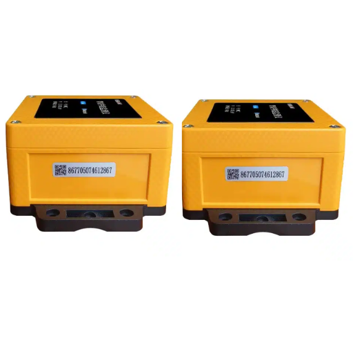
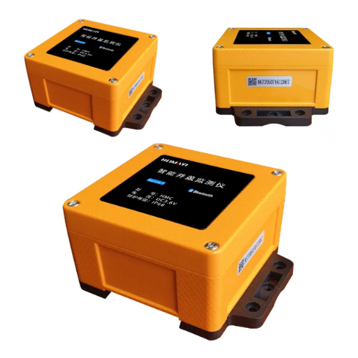
If you are asking what coordinate system IoT sensors should use, the hardware answer is settled. The module reports WGS84, and every other choice is a downstream decision. The device is rarely the source of the error, which is why replacing hardware in response to a coordinate problem usually wastes budget. What the device can control is what it stores and forwards. Black Ant’s smart manhole covers publish documented JSON over MQTT with the coordinate declared in the payload, so the receiving system never has to guess.
The middleware: the cheapest place to convert
The middleware layer is the last point where a coordinate can be fixed before it becomes permanent. That is the argument our MQTT to GIS middleware guide develops in detail, and the CRS decision belongs in the same place as unit and timestamp normalisation.
The rule that matters is transform once, at a defined place, and document it. If the middleware stores WGS84 and the GIS expects a local grid, transform on ingest, not on every read. Repeated transformations in a query path are a permanent performance tax, and each one is an opportunity for a different tool to apply different parameters. If your stack is QGIS, PostGIS, and GeoServer, the open-source pipeline guide shows the transform-on-write pattern in SQL.
The GIS: feature class, SQL view, and map CRS
Inside the GIS, three CRS declarations must agree: the feature class, any SQL view or layer published from it, and the map document that renders it. A map adopts the coordinate system of the first layer added to it, and everything else is drawn through an on-the-fly transformation. That is where a layer can be correct and the display still misleading. Our manhole asset data model guide covers where the CRS declaration belongs in the feature class itself.
Datum Transformations: Why “It Looked Fine” Is Not Enough
A coordinate transformation converts values from one system to another. A datum transformation handles the fact that the two systems describe the Earth’s shape differently, and it is the step people skip because they cannot see the result.
Missing transformation, wrong transformation, and the one-metre question
Skip a required datum transformation and the offset is not subtle. A mismatch at the ellipsoid level produces errors on the order of 100 metres. A missing +towgs84 or grid-shift term produces a smaller but still disqualifying error in the 2 to 4 metre range.
Both cases leave coordinates that look entirely reasonable. The question worth asking is not whether a transformation is needed but what accuracy the use case requires, which is why that decision appears later as its own table.
On-the-fly projection changes the display, not the data
This is the single most important operational fact here. When a GIS draws layers in different coordinate systems together, it reprojects them in memory for display. The source data isn’t modified.
Tomás Ferreira, a GIS lead at a Portuguese water utility, found the consequence. His map looked perfect: layers aligned, boundaries matched, nothing appeared shifted. But a buffer analysis returned wrong counts, because analysis tools run in each layer’s native coordinate system rather than the display system. The map was telling him the data was aligned. The analysis was operating on data that was not.
The lesson is simple to state and easy to forget: a map that looks right proves nothing about the data underneath.
Define Projection versus Project
Two tools with similar names cause a disproportionate share of damage.
- Define Projection overwrites the coordinate system metadata. It does not move a single coordinate. Use it only when the CRS label is missing or recorded incorrectly and the values themselves are right.
- Project recalculates the coordinates and writes a new dataset. Use it when you need the values expressed in a different system.
Confusing them is how a dataset gets “fixed” into permanent mislocation, because relabeling wrong numbers with the right CRS makes the error invisible rather than correcting it. Esri’s ArcGIS Pro documentation covers both tools and the transformation warning that appears when a layer needs a geographic transformation. If you are streaming telemetry into Esri’s stack rather than editing existing layers, the ArcGIS Velocity integration guide covers the ingestion side.
Vertical Coordinates: The Invert Level Nobody Checked

Horizontal position gets the attention. Vertical position decides whether a sewer model works at all.
An ellipsoidal height from GNSS is measured from the reference ellipsoid, a smooth mathematical surface. An orthometric height is measured from a geoid, which approximates mean sea level and is irregular. The difference between them, the geoid-ellipsoid separation, varies by location and can reach tens of metres. A municipal asset register stores invert levels as orthometric heights, because that is what a surveyor measures against.
A vertical shift may therefore be required alongside your horizontal transformation. A custom CRS definition can carry both, declaring a local elevation and a WGS84 elevation and applying the difference as a vertical offset. For a gravity-fed network, where invert levels determine flow direction, leaving that shift unhandled quietly corrupts every slope calculation in the model. Geoid models such as EGM2008 are the reference used to make the conversion.
Choosing a Transformation: Method Follows Accuracy
There is no single correct transformation, only one that matches the accuracy your use case needs. Choose the method from the requirement, not from the software’s default.
| Use case | Accuracy needed | Transformation class |
|---|---|---|
| Showing assets on a city web map | 5–10 m | Simple or none; verify visually |
| Locating a manhole for a field crew | 1–2 m | Standard 3- or 7-parameter transformation |
| Sewer hydraulic model, slopes | 0.2–0.5 m | Grid-based shift, current realisations |
| Survey-grade or boundary work | Under 0.1 m | Epoch- and velocity-aware, CORS-corrected |
Read that table before accepting any default. Every GIS ships a default transformation for a datum pair, and the default is chosen for general use rather than for your region or your accuracy requirement.
Fixed versus dynamic datums, and why epoch matters
A fixed datum is tied to a moving plate, so its coordinates stay stable over time. A dynamic datum is tied to the whole Earth system, so its coordinates change with the surface. NAD83 and ETRS89 are fixed in this sense; WGS84 and ITRF are dynamic.
The consequence for a sensor fleet is that the transformation between a fixed and a dynamic system includes a rate term.
A single set of transformation parameters captures the difference at one moment. If you produce coordinates from current GNSS observations, the parameters must be evaluated at the observation epoch. For metre-level asset work this is often manageable with a published transformation between current realisations, such as NAD83(2011) and WGS84(G1674). The NGS documentation of that transformation is the reference to work from.
The Pre-Flight Checklist for WGS84 vs Local CRS GIS Integration

Run these eight checks before the first packet is sent, and write the answers into the project file. Each one is cheap now and expensive later.
- Confirm the target CRS with the GIS owner, in writing. Ask for the EPSG code, not the name. “State Plane” is not a specification; EPSG:2226 is.
- Record the source CRS of every device. Assume WGS84 from a GNSS module, then verify it in the datasheet rather than assuming on the project’s behalf.
- Decide the transformation point and document it. Edge, middleware, or GIS. Pick one, state it, and make every party aware of it.
- Identify whether a datum transformation is required at all. If the source and target datums differ, it’s required, regardless of how small the offset looks.
- Match the transformation method to the required accuracy. Use the table above. Do not accept a software default without checking it against your region.
- Check units as well as systems. State Plane zones may be in US survey feet. A correct CRS with the wrong unit is still wrong.
- Confirm the vertical reference. Establish whether invert levels are orthometric, and whether a geoid-based shift is needed.
- Verify with one known point before scaling up. Send a single device or test record and confirm it lands on the correct manhole. One check catches the entire class of error.
If you take one thing from this article, take item eight. A single verified point is worth more than any amount of confidence in the configuration.
CRS in Tenders and Compliance
Coordinate systems stop being a purely technical question at procurement. Systems designed to different default CRS expectations will not interoperate without an explicit requirement to make them.
China: CGCS2000 is mandated, and platforms do not convert for you
Chinese deployments have a specific and easily overlooked constraint. Published patent documentation for a municipal data integration platform describes a requirement that cascaded and directly connected devices use the CGCS2000 coordinates defined by the planning and natural resources bureau map, to keep asset positions consistent across systems. The same document states that the IoT perception platform does not provide a coordinate conversion interface.
Read that carefully, because it inverts the assumption many integrators make. The platform doesn’t convert for you. If a project cascades device data into such a platform, the conversion is the integrator’s responsibility and belongs in the specification before pricing, not after commissioning. Our SuperMap iServer guide for China deployments covers the platform side of that architecture.
Standards default to WGS84, which is why your device is not at fault
Several standards settle the question in the same direction:
| Standard or platform | What it requires |
|---|---|
| OMA Mobile Location Protocol | Implementations must support WGS84 |
| W3C Basic Geo vocabulary | WGS84 for spatially located things |
| Korean TTA (outdoor IoT sensor location) | Defaults to WGS84 when no CRS is given |
| Aliyun IoT platform | Devices must declare a CRS; WGS84 and GCJ-02 supported |
The pattern is consistent: the transport layer assumes WGS84, the cartographic layer may assume something local, and nothing reconciles them by default. That gap is the integration work.
What to write into a specification
Three lines in a tender document prevent most of this. Specify the target CRS by EPSG code. State where the transformation is performed and to what accuracy. Require the supplier to prove alignment with a verified control point before acceptance.
A specification that says “data must be delivered in WGS84” is insufficient when the receiving platform is in a local grid, because it describes the source without describing the destination. Name both.
Conclusion

Coordinate system failures in WGS84 vs local CRS integration are quiet, which is what makes them expensive. The map doesn’t go blank. It goes wrong by 40 feet, or several hundred metres in China, and everyone keeps working until a crew cannot find the asset.
Five things are worth carrying forward:
- WGS84 (EPSG:4326) is what devices report; a local CRS is what your municipality usually works in, and the two need an explicit transformation.
- NAD83, CGCS2000, and ETRS89 each disagree with WGS84 for a different reason, at a different magnitude, and each has its own EPSG codes.
- GCJ-02 in China is an encrypted offset, not a datum issue, and it displaces assets by tens to hundreds of metres if you skip the conversion.
- On-the-fly projection fixes the display and leaves the data untouched, so analysis results can be wrong under a map that looks perfect.
- Transform once, at a defined point, and verify one known point before you scale.
The work itself isn’t large. Confirming a target CRS is a five-minute conversation with the GIS team. The reason it matters is that those five minutes decide whether your sensor data is useful or merely plausible.
Start with the checklist above, then confirm the coordinate your hardware actually reports. Black Ant’s smart manhole covers and IoT data collection terminals publish documented JSON over MQTT with the position declared in the payload, so the CRS question is answered at the source rather than discovered in the field. Read the full field-to-map GIS integration guide for the architecture around it, or talk to our application engineers about your project’s coordinate requirements.