

Balancing Valves: The Key to Hydraulic Stability in Large Buildings
For Marcus Chen, the alarm bells started ringing as soon as the conference room on the 28th floor could not provide its functions. February in Shanghai, outside temperatures reaching near freezing, and yet the occupants of the top three floors of the Jinmao Tower satellite tower were opening their windows because their spaces were oppressively stuffy. Meanwhile, the ground-floor retail spaces were freezing so badly that one store had broken out the portable electric heaters. Every bit of the $2.3 million worth of new HVAC system, installed just six months prior, provided the exact opposite of comfort.
They were not the chillers, boilers, or pumps to blame. The problem boiled down to the hydraulic balance, or rather the complete lack thereof.
When hydraulic water oscillates without balancing through pipes of a large built space, the vibration of physics steps in and costs come into play predictably. One path is almost always, going to get too much flow while the others, with more friction along those induction banks, will be the ones that get too little. As a result, the pumps toil even harder, in a frenzy through their additional losses in order to forcibly inject water in the direction that it would not take. Subsequently, some zones are overheated to obtain an increase in wear-and -tear and early breakdown, bar for the lack of heat in other zones. Energy wastage is multiplied 20%-30% higher than it should be.
Balancing valves design things up. With their intrinsic flow control sync, they ensure that their designed flow rates are provided to all terminal units of the hydronic apparatus—be it heating coil on the floor 42 or fan coil unit in the mechanical room of the basement. In further pages, the basic mechanism of hydraulic balancing, the role it plays in the functioning of large structures, and the selection process of manual or automatic (pressure-independence) approaches for specific cases would become much clearer.
Want to evaluate balancing valves for your project? Download Black Ant’s valve selection guide with sizing tables for DN15–DN300 applications.
What Is Hydraulic Balancing?

Balancing in HVAC is a process with the main objective of achieving the design flow rate through every terminal unit in a hydronic HVAC system. In its concrete meaning, balancing signifies that each coil or panel or heat exchanger receives exactly the flow that it was sized for; not more, not less.
Hydraulic facts are simple in the performance. While circulating water in a piping network with branches and all types of terminal units, inducers impose a pressure drop at each and every restriction associated with it. Without any balancing device, the natural distribution of flow follows the path of least resistance (another illustration of unwillingness by water not to flow into all terminal units). In other words, the closest terminal could get excess flow; the farther terminal could get insufficient flow. This phenomenon creates what has been known as hot and cold spots, the unwelcomed problem observed by all facility managers.
In large buildings, these dynamics get significantly more complex. The difference in static head pressure by vertical risers is exact. Economies of scale means that, not all terminal units are in operation at once. The variable-speed pumps modulate flow rates to meet the demand and hence change the system pressure at a continuous rate. System design practice takes for granted quasi-equilibrium regarding flow. Bringing flow balance under control requires some engineered solution.
Black Ant’s pressure-independent control valves (PICVs) combine differential pressure regulation with modulating control in a single device. Rated for PN16 and PN25 systems from DN15 to DN150, these valves maintain design flow regardless of system pressure variations — automatically compensating for the dynamic conditions that make large building hydronics challenging.
Why Hydraulic Balance Matters More in Large Buildings
In a way, the costs of incorrect hydraulic balance usually go hand in hand with the building’s size. A 5,000 sqm office building at the basement that lacks proper water system balance will be wasting power and getting widespread complaints of comfort from the occupants. On the other hand, a 50,000 sqm mixed-use tower impaired with similar mechanisms begins to effect tenant turnover, lease disputes, and equipment redundancies.
Another limit is raised by tall buildings. A thirty-story building causes a roughly 3-bar static head difference between the ground floor and the building’s top-most (30th) floor. If not sufficiently balanced, there would be a result for the cooling terminals on the upper floors, which would be deprived of flow, while in the lower floors, too much of it would build. The manu-ally set balancing valves instated during commissioning cannot actively react toward operation changes —and changes always happen.
Interestingly, the phenomena of district heating and cooling networks exacerbate both of these. For example, when one plant is ch=oosing to supply the multiple buildings that make up a campus, the hydronic imbalance in one building will spread through the entire network. The balancing valve is not just protecting the client-building’s own microclimate, but it is propping up an entire distribution system.
The True Cost of Hydraulic Imbalance

Most likely, facility managers end up recognizing hydraulic balance problems indirectly, wherein the noticeable symptoms manifest themselves and include complaints of discomfort, equipment callbacks, and energy bills unmet with expectations. As a rule, by this time, the symptoms begin to show, such hidden inequities translate into the wasting of money for some more months.
Energy Waste: The Hidden Tax
The uneven distribution of flow is wasting 20–30% of centrifugal pump energy, as implied by a recent study from ASHRAE. This has become an ever-increasing problem due to the incessant rise in energy costs. When multiple places see inadequate flows in comparison with the others, the system responds by bumping up pump pressure or simply inserting larger pumps, in which case more water is passed through the easiest routes. These are the routes which are already getting too much flow in any case, although the distant points may receive a slight advantage.
The mathematics are grim. In variable-flow systems, power of pump is proportional to the cube of the flow. For overcoming balancing faults, an increase of 20% in pump speed actually requires a 73% rise in energy consumption. And all of that energy will not be used for comfort but only to create overflow conditions that bypass any useful heat transfers.
Comfort Complaints and Business Impact
Sarah Williams found 47 open work orders to deal with heating complaints when her appointment to the services director for a 400-unit residential tower in Chaoyang District, Beijing was confirmed. The automation showed that all setpoints were met, the boilers were running, and the pumps were running. But tenants on floors 18-22 consistently reported cold apartments, whereas those between floors 3-6 were opening windows in January.
The root of the problem was hydraulic imbalance. The initial commissioning had been conducted with all units calling for heat at the same time — a situation that doesn’t occur in practice. When partial-load conditions came about because of real use patterns, the balancing valves wouldn’t adapt since they are the manual preset type. Flow moved along the paths of least resistance, dumping the upper floors.
During one heating season after their installation, the retrofitting of automatic balancing valves led to an 85% reduction of the complaint volume. The plant’s energy usage decreased 18%, going hand in hand with their moisture engineering updates. The plant went from spending three days each week chasing temperature complaints to hardly any time spent-especially needed by environmentally concerned practitioners.
Equipment Damage and Shortened Lifespan
Hydrodynamically, vastly disparate flow distribution usually leads to increased mechanical stress, rather than only energy loss. Immoderate velocities charge easily on valve seats, discharge headers, and pipe fittings. Cavitation originates when the head is reduced below vapor pressure, impersonating generated micro bubbles that implode against the metal surface with great force. A pump that is working so far away from the design curve begins to experience bearing loads and seal pressures that were never designed for.
Interesting enough, consideration of the entire life cycle of the system, a centrifugal pump operated at 150% of design flow will last 5-7 years instead of an expected 15-20 years. Increased rate of coil erosion in excess velocities would cause leakages necessitating repair. And to attend to these preventable failures in maintenance labor will draw resources away from more proactive system optimization.
Manual Balancing Valves: The Traditional Approach

Aforetime, manual balancing valves have been the darling of the HVAC industry for many decades. Indeed, these devices will create a resistance which will force the flow to distribute according to design intent. Balancing, to be reliable at all, must be carried out when these devices are appropriately selected and commissioned, within the constraints of their operating principle.
How Manual Balancing Valves Work
A Manual Balancing Valve has a variable orifice adjustment mechanism, a locking feature to prevent drift, and test points for flow verification. It is set by the commissioning engineer to force the design flow rate through this specific branch by imparting a pressure drop.
Each setting is manually tried until the design flow conditions are satisfied. For this purpose, the technician uses a differential pressure meter and adjusts the valve position accordingly while computing the flow rate from the Cv or Kvs curve from the valve manufacturer. Since each variation affects the whole system, this procedure is carried out until all the terminals reach design flow all at once, a situation that requires only many iterations around the building.
When Manual Balancing Makes Sense
Manual balancing valves remain cost-effective for some applications. Small systems without a lot of terminal units or load variations, for example systems with less than 50 terminal units, perform quite adequately with manual valves. Doing this really saves money in terms of the initial cost; a manual balancing valve would cost 30%–50% less than an automated valve with the same flow capacity.
Manual balancing also works well in constant-speed pump systems, particularly those with fixed fan speed. The preset valve postures are suitable if the operating temperatures represent almost all times at one design boundary. These describe some of the industrial process applications, educational buildings built decades ago, and the cheapest house jobs. In these cases the priority is definitely towards initial cost, relegating questions of operating efficiency.
The Limitations That Matter
The primary limitation with mere manual balancing valves is: they are static. They cannot adapt once set into the system. This would cause problems under three most common conditions:
Part-load operation: When the terminal units modulate to a closed position by reaching thermostat on-off cycling, the pressure in the system increases. During a manual valve open, it cannot increase the resistance to balance the flow between remaining open terminals. The excess flow causes the pump to work against a greater head pressure.
Seasonal variation: Heating and cooling seasons present major variations in demand for flow. If a manual valve is balanced for chilled water in the summer, there is no proper balancing for hot water in the winter. A user could accept bad performance or pay a huge sum to retune the valves-which is an extremely expensive and often glossed-over act of maintenance.
System modifications: When tenants want to remodel, equipment has to be replaced or there is any change in building use regarding the original balancing setting, which makes it useless. The entire commissioning process has to be conducted afresh to check and establish new balance points.
Black Ant’s manual balancing valves have precise adjustment mechanisms, position indicators, lock nuts to avoid drift, and test ports compatible with standard balancing devices. These valves can be used to balance the system manually when the application ideally requires it, wherein the DN15–DN300 size range covers almost all commercial HVAC requirements.
Pressure Independent Control Valves: Dynamic Solution
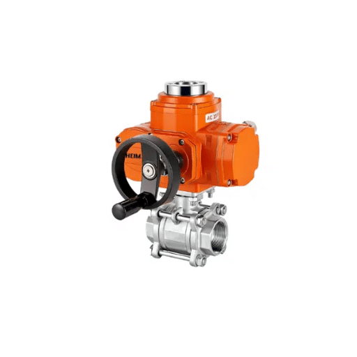
Pressure-independent control valve (PICV) is a quantum leap in hydronic system design. Through the automatic regulation of two mechanisms — differential pressure and a modulating control valve — the PICV maintains the specified system flow irrespective of changes in pressure due to other terminals cycling on and off.
How PICVs Work
A PICV consists of a neat internal structure. The pressure control cartridge reads the differential pressure across the valve and sets a closed-loop controller accordingly to maintain a constant pressure drop across the control orifice. This decouples the terminal unit from variations in system pressure.
For example, if a PICV is set to deliver 0.5 liters per second to a fan coil unit, it will deliver 0.5 liters per second regardless of whether the system pressure is 10 kPa or 100 kPa. As the other terminal units in the system are modulated closed, the available pressure becomes higher, thus further tightening the PICV’s controller to compensate. In this case, the control valve “sees” a constant differential pressure across it, meaning that its flow characteristic (linear, equal percentage) is highly predictable and stable.
The automatic balancing removes any manual re-commissioning exercises. Set the valve at the design volume flow rate often by utilizing a dial or digital interface, and this is the value flow delivered by the system Commissioning time reduced by 60-80 percent as compared to manual balancing procedures.
Energy Savings That Pay Back
A PICV saves a considerable lot of energy, and the energy savings there are substantial and well proven. CIBSE and ASHRAE studies recorded 20%-40% less pump energy—greatly off manual balancing systems. The mechanics is straightforward:
- Low system pressure is sustained since the PICVs do not need extra pressure to force the flow through fixed resistance,
- Variable speed pumps run at lower speeds to ensure the minimum required pressure
- Overflow is physically impossible.
- The pump curve automatically optimizes itself instead of having a complex control sequence instituted to bear pressure exceeding the design point
Have in mind a saving range at typical conditions for an HVAC-intensive, 50,000 sq. m. commercial building from 150,000–250,000 kWh annually. On present industrial electricity rates, the period for repayments in upgrading from manual to automatic balancing falls between 3 and 6 years—within the provisioning horizon of your facility.
PICV Variants and Selection
Different PICV configurations can manage different application settings:
valve types: There is either two-way or three-way configurations. Two-way PICVs are typically used in variable-flow systems, where the return volume of water varies with different loads. The three-way PICVs control constant flow into the terminal with modulating bypass; a choice for constant primary-flow circuits or those that require minimum flow guarantees.
Characterization: The control valve could have either linear or step characteristics. Linear types are employed in fan coil units and applications where flow’s physical position determines valve position. Step control is better for heating bundle coils and systems with variable heat transfer coefficients.
Actuation alternatives: Electronic actuators with BMS-enabled control signals—typically 0–10V or 4–20mA—can provide precision feedback. If you favor simplicity and require only on/off control or fully floating control via a simple switching device without all the electronic goodies, consider going with thermal actuators. Thermal-electric hybrid actuators strive to strike a balance between response time and power consumption, allowing operation with either battery-powered hybrid actuators or in energy-harvesting scenarios.
Black Ant’s PICV ranges from 15 DN through 150 DN Kvs values range from 0.25 m³/h to 320 m³/h. By using inductive stroke measurement, differential pressure regulation sensitivity is maintained within ±5% of the rating running range. There are communication options including Modbus RTU and BACnet MS/TP for direct control device positioning feedback, flow measurement data, and troubleshooting.
Applications in Large Building Types
The hydraulic balancing requirements vary significantly across building types. Understanding these variations helps specify the right balancing approach for each project.
High-Rise Commercial Buildings
The building’s height poses specific challenges when a plant is over 20 stories underway. Pressure differences of static heads specific to the floors require serious analysis. Historically, this necessitated a different approach by establishing intermediate-pressure reducing valves across building-length hydraulic regions.
These days, the economic use of PICVs all through the building is considered a better approach presumably, as designers can size up their differential pressure rating (accept PN25 rather than PNl6) to surpass the static head. This leads to an easier design, eliminating the hidden cost of intermediate pressure-reducing stations, and ensuring a consistent control across every single floor. This in turn will yield unseen benefits, in particular, for high-rise applications as the pump head required to lift the static body is much, therefore any efficiency gain is hugely catapulted across a large pressure differential.
Healthcare Facilities
Hospitals and clinics have the most stringent requirement for control. Operating rooms, patient rooms, and critical-care areas simply cannot tolerate any temperature drift. Many spaces demand 100% outside air and consequently have huge heating/cooling loads that have to be consistently satisfied.
The redundancy aspect is also vital. If there is a switch-over due to redundant pumps or chillers, system pressure dynamics will change. PICVs automatically adapt to these changes so as to allow the flow design to get to the critical terminal irrespective of the available equipment. A manual valve would require re-balancing every time the equipment/valve is changed, which is impractical for an operation that lasts 24/7.
District Heating and Cooling Networks
Balancing within the building and across the District Circuit becomes a huge issue for DE systems serving multiple buildings from the central plant. PICVs play a major role not only in safeguarding the internal hydraulics but also creating expected flow appropriateness within the district loop.
This predictable behavior matters to plant operators. Once all buildings upstream maintain an equal flow rate regardless of what the downstream load has to offer, this central supply sees a very stable king of turnover. This, in turn, supports pump optimization. Moreover, energy billing is ensured no longer to be inaccurate with ever-changing flows due to pressure changes in the system.
Black Ant’s ultrasonic heat meters integrate directly with PICV installations, providing MID-certified energy measurement for district heating applications. The combination of precise flow control and accurate thermal measurement creates a complete solution for modern heat network requirements.
Selection Guide: Choosing the Right Balancing Approach

The decision between manual and automatic balancing depends on system characteristics, operating patterns, and lifecycle cost considerations.
System Size Thresholds
Standard practice indicates that certain directives exist for variable flow:
- Less than 50 end units: manual balancing could yet be successful if loads are nearly constant
- 50–150 end units: balancing requires a variable flow evaluation, with the pressure independent control valves (PICVs) consistently the winners for variable flow systems up to this size
- Over 150 end units: There is no way to meet the balance between costs and benefits for the PICVs. The time saved earned during commissioning often pays alone for the valves.
Consequently, the grouping encompassed by these thresholds would be primarily related to commercial HVAC. The industrial process is likely to be similarly rewarded with manual balancing at higher numbers. Applications with high value (e.g., healthcare and data centers) could qualify as early as PICVs for a smaller scale application, as maybe these structures demand 100% reliability.
Load Variability Analysis
The essential question as to whether your system would respond to pressure fluctuation during normal operation. In the instance whereby the rate of the control valves employed in the terminal units modulate in sync with a setback by a thermostat or HVAC controls for gradual control of heating with changing outdoor temperatures, then yours is a variable-flow system and would benefit more from PICVs. Manual balancing could be enough if it is on-off (whether fully open or fully closed) with respect to the terminal units. If terminal units modulate and the pump speed is fixed, the manual balancing might be sufficient.
Modern commercial buildings universally follow the variable speed control system and work with variable speed pumps, two- or modulating-position control valves, and variations related to the demand drive. These dynamic on-load conditions are designed for PICVs.
Total Cost of Ownership
First-cost comparisons favor manual valves by 30–50% on a unit basis. But lifecycle cost analysis often reverses this conclusion:
|
Cost Component |
Manual Balancing |
Automatic Balancing (PICV) |
|---|---|---|
|
Valve hardware |
Lower |
Higher |
|
Commissioning labor |
High (iterative process) |
Low (preset and verify) |
|
Seasonal rebalancing |
Required (often neglected) |
Not required |
|
Energy consumption |
20–40% higher |
Optimized |
|
Maintenance/replacement |
Higher (erosion, damage) |
Lower (protected operation) |
Over a 15-year building lifecycle, the operating cost savings from PICVs typically exceed the first-cost premium by 3:1 to 5:1.
Integration with BEMS and Smart Building Systems
Modern balancing valves have come of age as smart field instruments as they provide accurate data to the building energy management system (BEMS)and can, in turn, contribute to predictive maintenance schemes.
Smart PICV Connectivity
Balancing Valves when equipped with such network-controllable wiring control, transition them into a node. Field devices present position feedback to tell the BMS the condition of its supply: open, close, partially open. The value for energy conserved for flow calculation is based on the position of the valve and the differential pressure, thereby presenting real-time energy use data. This data will allow an alarm condition to be flagged and flagged when the actuator is out of the allowed tolerances, with the valve stuck, flow outside tolerance, and valve actuator faults, which ills require workflow maintenance occurrences before any tenant complaints are made.
Black Ant’s PICV actuators support Modbus RTU and BACnet MS/TP protocols, ensuring compatibility with major BMS platforms. The communication module provides position feedback, flow estimation, and fault status to the central system. Configuration parameters — flow setpoint, control characteristics, timeout values — can be modified remotely without site visits.
IoT Data Collection and Edge Analytics
For buildings without comprehensive BMS infrastructure, or for portfolio-scale monitoring across multiple properties, IoT data collection terminals provide an alternative integration path.
Black Ant’s IoT Data Collection Terminal connects to PICV actuators via RS485, aggregating data from up to 32 devices on a single communication loop. The terminal transmits to cloud platforms via NB-IoT, LoRaWAN, or 4G cellular — no building IT network required. Edge computing capabilities enable local analytics: trend analysis, anomaly detection, and automated alerts without cloud dependency.
Battery-powered options (6-year life) eliminate wiring infrastructure for retrofit applications. This makes comprehensive monitoring economically feasible even in buildings where running new cables would be disruptive or expensive.
Predictive Maintenance Applications
Valve position data opens doors to predictive maintenance strategies previous generations thought were impossible, thanks to the mechanics underpinning the device. A valve that never reaches the closed position could be an indication of equipment that is oversized or a bad temperature sensor. Rapid cycling with a valve suggests poor control loop tuning. Position drift over months indicates that a filter is loading or the coil is fouling while still being able to give warning before performance starts to deteriorate for visible reasons.
These insights shift maintenance from reactive-fixing failures-to predictive-addressing degradation before failure. For a facility looking out for thousands of terminal units in multiple buildings, this data-driven approach will completely transform the economics of maintenance.
Installation and Commissioning Best Practices
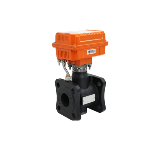
Proper installation ensures that balancing valves perform as designed. These guidelines apply whether you’re installing manual or automatic valves.
Design Phase Considerations
Valve sizing: Balancing valves should be based on flow rates and pressure drops—not pipe sizes. An oversized balancing valve, i.e., sized based on pipe diameter rather than flow, engenders poor authority in valve. The valve should be in a flow situation that works off between 50% and 100% of its rated range, thus leaving some room for variations in the future and granting flexibility in its control that is accurate.
Location accessibility: If someone asks, you should install balancing valves, as they are then capable of being monitored, adjusted, and maintained. It may seem obvious, but any valve buried conveniently above ceilings or lost behind machines immediately becomes a “set-and-forget” mentality — which means they have not been used to their potential. Access doors should be considered with working space and well-balanced lighting.
Isolation valve coordination: Balance valve itself is enclosed with good isolation valve upstream and downstream. This enables removal or replacement of the balance valve without draining the whole system. An extra amount invested in isolation valves can be amortized repeatedly with the reduced downtime associated with maintenance.
Installation Guidelines
Flow direction: Most balancing valves are directional – they must be installed with flow matching the arrow cast into the body. Reversing installation, in this case, means losing the pressure regulation function and more than likely controlling unstable.
Pipe length: Control valves need enough straight pipe ahead of themselves to ensure a stable comfortable flow profile. Follow the manufacturer recommendations which typically ask for 5 to 10 pipe diameters upstream and 3 to 5 diameters downstream. They are the traditional actuators, in comparison, which are far more sensitive than a PICV and can be lost if an incorrect inlet condition is corrected.
Strainer protection: Install strainers ahead of balancing valves, especially in open systems or those where debris from construction work may be present. The picv cartridge has tiny precision places that can plug with particulate. A simple Y-strainer would be a good investment to protect this delicate PCV arrangement.
Commissioning Procedures
Human-induced valve set-up: starting from the one at the farthest end from the pump and terminating in balance; then go back to the main source input. Take records of the various positions of the valves. This balance is expected to require more than one iteration because relative movements will need further fine-tuning.
PICV commissioning: PICV commissioning follows a much simpler path. Position each valve to design flow with the adjustment device. Verify that the actual flow with portable meters (taking between 10 and 20% of the total number of terminals suffices). Test control responses from the BMS. Document these settings in the permanent building records.
Black Ant assists the user right from commissioning inception and has provided field assistance during startup, checks of the terminal control sequence, and operator training. For larger projects, our applications engineers can perform submittal reviews during the design process and field visits for the most critical commissioning tasks.
Conclusion
Hydraulic stability just doesn’t happen. Engineers must actively enforce the comity of pressure and flow in large buildings with complex hydraulic systems, as these physical processes apparently never offer balance. Balancing valves—whether automatic or manual—are the tools that prevent design from being defeated by the intrinsic traits of water to take the path of least resistance.
The preference for the two balancing methods is in essence one of economics. Manual balancing valves come at relatively lower costs, but incur higher expenses for installation and startup, consumption of energy, and maintenance. On the other hand, pressure-independent valves cost more initially while utilizing their commissioning efficiency, variable-energy demand savings, and adaptiveness, which manual types cannot.
In sum, the vast majority of modern development of commercial buildings, specially for those larger than 50000 m2 or with variable-flow systems, should opt for PICVs by engineers. The manuals are no longer advantageous for good PICVs in buildings of a size above 50000 m2 or any systems with variable flow.
Key points:
- An undersized or oversized system should prove inefficient in utility capital, even with acceptance of undue operational risk, whereas a finely balanced system could serve with acceptance of a safety margin of ±10%
- Manual balancing valves are effective for small, constant-flow applications, but they are unable to adapt to changing conditions
- Applying a pressure-independent control valve gives the benefit of automatic set-point control that results in up to 60-80% and 20-40% reduction in commissioning and energy consumption, respectively
- Moreover, the BMS/IoT platform integration of a PICV shall provide the facility or building manager with all pertinent data to inform decisions about the system’s maintenance minds, all while allowing fine-tuning of the system for peak performance
- A PICV has always proven most advantageous in the long run with respect to the price of ownership for over 50 terminal units or variable-flow system applications
If you’re specifying balancing valves for a commercial HVAC project, Black Ant’s PICV range offers DN15–DN150 sizing with Modbus/BACnet connectivity, precision differential pressure regulation, and the engineering support to ensure successful implementation. Contact our applications team to discuss your specific requirements or download the complete valve selection guide with sizing tables and specification sheets.







