

Minimizing Cavitation in Electric Control Globe Valves
Cavitation arises as one of the primary challenges faced by some electric pneumatic globe valves in industrial fluid control systems. Common symptoms increase when the damage is caused by cavitation and wears on the valve system, making it inefficient and highly demanding where rectification in a short period would be very costly. What is cavitation and how do valve components internal in the system impede performance while reducing the effect of cavitation within the system? This article explains real cavitation phenomena: its causes and effects and discusses the major strategies for controlling it. Any engineer seeking information on the system of cavitation control system Laplace can use this piece to improve the reliability of the system or vice versa to generate a better understanding of flow dynamic control principles that are more extensive. In this context, readers may find many advantages for optimization of the valve system in general.
Cavitation in Valves: An Overview

Cavitation takes place in control valves when the pressure of a liquid falls below the vapor pressure, creating vapor bubbles. When vapor bubbles impinge on a wall downstream, the possible damage is perceived by the operator and the management, while collapsing at high velocity due to rebound pressure. Cavitation largely damages both valves and piping beyond that point. Specific repercussions for valve systems would be efficiency, reliability, and life. The crucial point is the understanding of designing conditions for cavitation — while incorporating the mechanisms for design and operational means to prevent cavitation. Essential instruction with respect to this direction should involve factors like the valve type, proper control of pressure differential, and the production of liquid flow paths.
📖
Definition of Cavitation
Cavitation is a series of rapid pressure changes in liquid that results in the formation and dissipation of vapor-filled bubbles or cavities within the medium. This occurrence usually happens when the liquid is subjected to below ambient pressure, exceeding its actual vapor pressure, causing vapor bubble formation. These bubbles violently implode upon entry to the higher pressure zones and exert sufficient force to generate high-power shockwaves backing up the pump impellers, pipe walls, valve parts, support, or any other equipment part that may be affected.
There have been recent studies which have attributed mostly cavitation to issues like those wherein there is a flow distinguished by a high velocity of fluid particles falling in vortex with the pressure drops causing a rise of vapor bubbles in the cavitation process. It has been reported that by forming cavitation of vaporization, the precipitation of intense localized temperature peaks with temperature in excess of 10,000 K and pressure up to 1,000 atm comes to yield results in significant material debauchery complementing the loud, massive vibrational production at the time of bubble collapse.
If, for instance, cavitations on ship-propellers may substantially decrease their overall efficiency and hence increase fuel use and interrelated maintenance costs, then industries are continuing to experiment with advanced computation fluid dynamics (CFD) practices as well as vibration control engineering to neutralize cavitational effects. Strategies such as decreasing pressure drops, elevation of resistant material technology for cavitation, and smoothening of flow passages give scores to counter cavitations and its adverse side effects. These measures can eventually help improve the reliability and durability of hydraulic equipment or machinery under industrial and environmental conditions.
Impact of Cavitation on Industrial Operations
The adverse effects of cavitation toward any process, but particularly those based on liquid flow under high pressure, rank among the most concerning of all. Outlined below are five primary situations that occur when cavitation is produced through a given set of disintegrations and any related associated data or explanation:
1. Erosion and Damage of Material
The strong shock waves on cavitation bubble collapse generate material erosion and pitting on the surfaces. In a test about cavitation, it was observed that turbine blade losses could exceed one millimeter per annum (and as much as 8 mm) owing to cavitation erosion in hydroelectric power plants.
2. Decline in Efficiency
The caval cavitation makes the systems work inefficiently by hampering the free flow of fluid within them. Cavitation in a centrifugal pump may lead to an efficiency loss of 15%, showing tremendously bad consequences in terms of the performance of the systems.
3. Vibration and Noise
Cavitation is very likely caused by an implosion of the vapor bubbles created around the peak pressure location of a breakdown to reach the homogeneous antinodes and nodes, pinpointing the enveloping structures since the vibrations and noise stemming from the cavitation melt equipment and the industrial environment in the process while having the plant compromising its safety and regular functionality. In this case, the structural tests showed evidence that cavitation-induced vibration could increase beyond allowable operational limits of machinery and could thus reduce the service life of machinery.
4. High Maintenance Costs
Equipment subject to cavitation experiences major impacts on maintenance costs, which are notably higher. A major multicenter plant investigation shows that the maintenance costs on the afflicted percentage were higher compared to the nonafflicted community by 25-30%.
5. System Failure
Speaking briefly, cavitations are understood to have a regulatory connection that leads to a breakdown of the implant interspersed with wear and tear of some individual units downstream. An example of this was provided by one ship propeller whose suffering cavitating observed compressive cracks and other types of cavities that practically halved the longevity of the affected parts.
In view of the consequences, the gods are inclined to maintain the functionality and lifespan of the industrial systems. The need for effective loss prevention must remain paramount.
Overview of Electric Control Globe Valves
Electric control globe valves distinguish themselves from flutter valves in industrial situations and aims to manage the flow of a fluid. The “electrical” portion by itself conveys an automatic control, and the application of this technology provides for fine control over variables — such as flow, pressure, and temperature — that industry is so heavily reliant upon, be it for oil and gas production, chemical processing, power generation, or even climate control.
🎯 Manufacturing & Selling
Electric Control Globe Valves are extremely accurate in directing the flow of fluids. Applications vary from modulating the flow in a linear or an equal percentage while modulating is a critical necessity to maintain process control at a high level.
🔩 Range of Materials
Made of different materials including carbon steel, stainless steel, and exotic alloys, electric actuated globe valves can be used to control a wide range of media, including water and steam and all corrosive chemicals and abrasive slurry.
🛡️ Durability & Reliability
Electric actuated globe valves are capable of working in high temperatures and pressures with minimal maintenance requirements when exacerbated by rigorous conditions.
⚙️ Automation Input Capability
The present-day electric-operated globe valve is provided with compatible automation systems that rely on real-time feedback from smart positioners, sensors, and remote-monitoring capabilities for more efficient system control and the elimination of human errors.
Technical Specifications
📊 Performance Data
Electric control globe valves are presented throughout as the high beneficiaries of the industrial data and its operational benefits owing to potential system deficit of about 20%. Their high sensitivity enhances the system capability to perform flow-fully — quite precisely over a large range of settings. For instance, in MWh terms, valve energy savings are expected to stand at around 50% — a good improvement on pipe network efficiency, as in one of identical construction, but with a manual ball valve as an actuator, giving valid waste, not too bad in fact. The incorporation of predictive monitoring to condition maintenance may reduce unplanned downtime, lower the extent of slip-ups to 15-25%, and improve industrial output over the long term.
Applications
The automation of process control can efficiently contribute to more precisely and possibly enough maintained and taught process of having (by automation) a plant together by it.
The Mechanics of Cavitation in Globe Valves
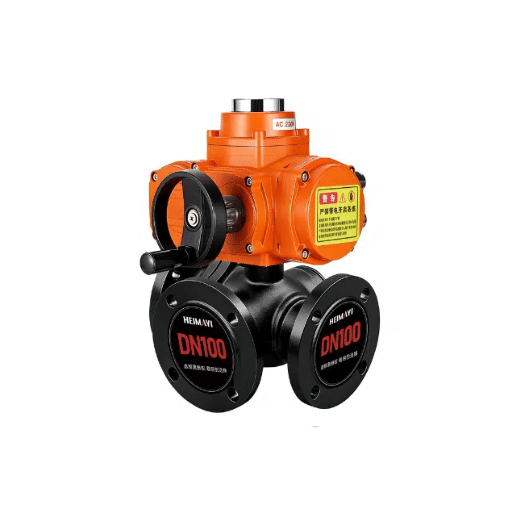
Cavitation: mandatory to be careful about that on the globe valve. What is cavitation? This mechanical phenomenon occurs, specifically, when fluid pressure transiting the valve dipped below the vapour pressure and caused vapor bubbles in the liquid. These vapor bubbles implode almost immediately as the pressure recovers towards an equilibrium state within the system. The sudden local shock waves generated by the bubble choking the valve due to collapse exert high shock stresses on the valve components, which could over time lead to corrosion, noise, vibration, and dropping efficiency of your valve.
Several factors lead to cavitation in a globe valve and are, in turn, influenced by the speed of fluid, fluid properties, pressure drop across the valve, etc. Cavitation is likely to take place in high-pressure applications, where a substantial reduction in pressure is about to happen. Based on fluid dynamics research, cavitation is induced when the pressure coefficient fell below a definite threshold.
Cavitation Information & Differentiation in Globe Valves
Once we have understood the idea of cavitations, different industries can take some effective counter-measures to improve the working life and performance of globe valves, creating ever more reliable and efficient operational systems.
Causes of Cavitation in Control Valves
Cavitation may happen in the control valve as fluid runs through the valve since the fluid causes this rapid depressurizing over the valve. If the pressure falls below the vapor pressure of the fluid, the mechanism causing bubble formation arises. If such bubbles manage to move to the pressure zones downstream, where the prevailing pressure is high, they only collapse suddenly. This imparts an intense jet of high-temperature and high-pressure on the valve component that could possibly destroy the valve parts. There are essential causes of cavitation in the control valve:
-
🔴 Differential Pressure High
This brings fluid pressure down so low that it falls well below its vapor pressure, thus allowing ideal conditions for the fluid to incessantly turn into a vapor bubble; studies have shown that pressure-drop increases above the threshold, exponentially increasing the dangers of cavitation and often depending on fluid type and system design. This generally comes about here through water applications where the pressure at near vena contracta is much lower than that in the downstream portion.
-
🔴 Valve Sizing and Flow Properties
Incorrect valve sizing, or functioning, leads to the generation of conditions favorable for the creation of cavitation in themselves. Requirement failures together with cavitation are always an outcome of turbulence and local pressure drops with a partially opened valve. From a technical point, globe valves downscaled in size to withstand constantly fluctuating flow rate conditions pose a serious threat, supported by excessive flow restrictions.
-
🔴 Properties of Fluids
In general, low-vapor-pressure fluids (such as H₂O, certain hydrocarbons) are highly prone to cavitation. Some fluids similar to water are obviously characterized by cavitation while considerably different fluid types, such as hydrocarbons, propane, ammonia, and many others, frequently having industrial applications, introduce some variant rationale for cavitation risk.
-
🔴 Flow Velocity
If the fluid velocity on a valve’s suction side is allowed to exceed certain limits, cavitation may start due to low-pressure cavitation bubble implosion. Most cases demonstrate that a 20% increase in velocity cleanly doubles cavitation occurrence within a possible 30-40% range whenever industrial applications are present. Thus, the valve size and flow control become absolutely mandatory aspects.
-
🔴 System Design and Layout Issues
Improper piping configuration leading to unstructured upstream flow (in terms of straight pipe sections), causes uneven velocity distribution. The simulation argues that severe changes in the pipe diameter or any sharp bends in the pipe before the valves may create different combinations of turbulence and pressure transients, thereby leading to cavitation.
By considering these basic factors in a system analysis (in terms of system parameters), an engineer will be able to identify and decrease these aggravated events of cavitation by properly executing countermeasures, such as anti-cavitation trims, customizing and specifying the right valve type and advancement in better piping layout.
Specific Dynamics of Electric Control Globe Valves
Electrically controlled globe valves play a critical role in a fluid transmission system where precise control over the flow, pressure, or some temperature is needed. An electric actuator moves the globe valve spool to finely control the spool position in order to enable quickly responsiveness to dead conditions, thus very accurate control is obtained. The seat and plug are designed in such a way that when tight or holding high-pressure differentials, there will be no leakage.
Technology evolved and changed the modus operandi of gloomy traditional control valves to electric pneumatic control valves with the same electronic intelligence. The modern electric control valves and globe valves allow the assembly of intelligent control systems and very intelligent actuators based upon the advanced digital assets. Some control valves can be digitally measured, assuring the control impossible without monitoring of parameters related to safety and process within the industrial exchanges. Parallely, the control valves might hold a direct control system with the data gathering in real-time via DC signals.
And if the lack of preventive measures is often blamed for the dangerous situations, some advance techniques have been developed to be used more effectively with embedded brakes as now argued the strategic concept of building a fully automatic deceleration system.
±1%
Accuracy from setpoint in optimized systems
<1s
Response time for most services
500K
Strokes life under normal operating conditions
The valve flow coefficient (Cv), the input pressure, and the output pressure, as well as the fluid properties, are all important factors that influence the dynamics of some control valves. By all estimates, CFD analyses, i.e., Computational Fluid Dynamics, seem like the best alternates, in the opinion of most engineers, to evaluate its dynamic performance under different conditions and ensure the valve operates satisfactorily as per the needs of the operation. The same kind of evaluation also supports the sizing and rating of the valve correctly for desired maximum efficiency and longer life.
The power of the design, and the robust assembly combined with modern-day technology make electric control globe valves truly a force demanding respect for their reliability and coping capacity for modern fluid control challenges in every domain.
Key Strategies for Minimization of Cavitation

1. The Most Suitable Selection of Valves
Proper sizing is crucial when considering the right size of the valve (to have your control valves sized to further optimize its performance.) An incorrect valve size results in ‘unstable flow’. This exposed position invites a high risk of cavitation to enter the space. CFD analysis needs to be employed and use tools those clients claim to size control valves to size Vee Needles properly in accordance with your industry.
2. Avoidance of Pressure Drop
Multi-layered pressure reduction is the ideal design policy if you want to reduce pressure across the valve. Alternatively, little-known trims are available that are highly resistant to tolerance of high pressure difference. This process also stops acute pressure loss, restricted pressures to drop below vapor pressures, and subsequently eliminates cavitation.
3. Anti-Cavitation Valve Trims
These are unique trims as they help in controlling energy dissipation and manipulate the flow velocity in a way that it lessens cavitation damage by causing fluid to fragment into smaller jets and provide lesser velocity to facilitate pressure recovery without the formation of vapor bubbles.
4. How to Use Cavitation Predictive Tools
They need to use predictive models and diagnostic tools to mark potential cavitation zones in the system. CFD simulation and flow analysis tools further help them project and subdue possible cavitation risks ahead of time.
5. Material Selection for Cavitation Resistance
Valve materials along with their trims must be cavitation abrasion resistant. Use of hard alloys, stainless steel or any other hard material is too often suggested to help escape from abridging the life of the valve under cavitation conditions.
Implementing Multi-Stage Trim Solutions
Multistaged trims are designed to reduce pressure in several steps; these steps in a series of adjustments toward this end ensure that the fluid pressure does not fundamentally drop suddenly enough to cause cavitation or flashing.
🌀 Flow Paths
Flow paths are usually designed so as to each become channels, upon each of which an array of more labyrinths obstruct the full flow of the fluid, thereby giving the fluid least resistance after it flows over the pipe and restores an entire effect of entrails which go on becoming intensely more complicated until they are on haunt — a contrivance operating to torpedo the speed of fluid, maintain the step-by-step actual pressure conversion, and reduce energy losses.
🔧 Material
In simpler thoughts, multi-stage trimming is made from the erosion-resistant spray steel, such material capable of surviving the turbulence of fluids and wear of particles.
🔊 Noise Reduction Technology
By enhancing a multi-stage design, you can design sections for diffusion or continuity of sound, creating an attractive panel in an environment where there is high demand for acoustic performance.
⚙️ Bespoke Configurations
Trims can then be designed in different shapes or sizes to best fit the situation and application needs. Their hydrocarbon characteristics, flow, and operating pressures would all shape the performance of the joint design.
The elements listed lead to an increasing preference for this kind of degasification. Certainly, any one of the potential two-stage applications would provide increased finesse or performance at the expense of higher efficiency and pressure drop, respectively.
Managing Pressure Drops Effectively
A considerable reduction in pressure losses is imperative to system efficiency and safety due to occurring across a chain of industries. Pressure drops could happen as a liquid travels through pipelines, orifices, or fittings. Optimizing the same becomes more of a necessity in that it would reduce power wastage and optimize operational efficiency.
Insert no doubt that deploying specifically carved multi-stepped needle-trim geometry could reduce the pressure drop along the operating range. Deployment of this technology in the long run limits the creation of turbulence-erosion, ensuring sustained smooth flow control. Again, an example — usually, the elimination brought about by the multiple trim stages pertaining to cavitation and, hence, reduce the wear in valve parts by 50%. These solutions bring about cumulative benefits to an increasingly extended duration of high operational dependability due to excellent flow characteristics.
To distinguish its method of utilizing logical pipe selection with low elbow turns, enhanced field efficiency would invite an appreciably reduced pressure drop. References suggest that an erroneous pipe size of pipe over-sizing will tend to reduce the in-line yearly loss by 20-30%. With the cost implication here, this loosely translates into using bigger pipes because the jobs would spend more on materials owing to the waste. But the maintenance of the system is paramount and pays off since it will restore pressure efficiencies through the removal of blockages and the observation of signs of damage.
📡 IoT-Based Remote Monitoring
On the other hand, there is a resurgence of pressure drop management through remote monitoring systems based on data. Pressure sensors empowered by IoT can govern almost every flow and real-time changing pressure values, subsequently ensuring real-time operators’ responses. Thus, hardware-based predictive maintenance empowering a rise in system efficiency by almost 15% will be a backbone to operational flows into the system.
Switching between advanced technologies and constructive design enhancements could maintain system stability with less energy consumption while providing major performance improvements when the system is under high pressure.
Choosing the Right Materials for Valve Trim
Material choices for valve trim are critical for longevity, efficiency and reliability in an environment of high pressures and severe service. This is because the components of the valve trim, the plug, seat, stem, and cage in various configurations, are likely to operate in a number of operational states with high temperatures, extremely corrosive chemicals, and high stress levels. In every aspect relating to the selection of materials, wear resistance, corrosion resistance, and mechanical integrity are the topics to reckon upon the stresses that will develop owing to the service environment and the use of such materials.
Common Materials Used in Valve Trim
Key Selection Considerations
- Operating Temperature and Pressures: Material selections will require the highest operating temperatures at the design environment laid down and without any detrimental form of deformation under thermal or other applicable stress.
- Corrosion Resistance: It’s an undesirable situation to deal with materials with detrimental effects like corrosion, pitting, or stress cracking.
- Mechanical Properties: The materials need to have their own peak hardness and strength as indicated by the application of repeated loads and wear resistance.
- Cost-Performance Tradeoff: Materials such as Hastelloy, for example, have a high initial cost, but this usually gets countered in the long run by service improvements in the useful life of the material.
📊 Data Shows
As per recent research, hard-alloy valve-trim pieces made with advanced nickel-based materials are lasting to 40 percent higher in the most corrosive of environments, thus decreasing downtime and maintenance costs. Carbide-coated valve-trim parts currently recorded a wear rate decrease averaging nearly 50 percent under abrasive environments, hence enhancing the integrity further.
Maintenance and Monitoring Techniques

Definitely, in any industrial system, the topic of monitoring and maintenance of reliability-in-the-lifetime is of critical importance. A mixture of preventive systems and technologies can make the systems more reliable and also minimize equivalent costs to a high degree.
🔍 Predictive Maintenance
Predictive maintenance (PdM) is about accurately predicting the occurrence of any prospective failure, based on timely and enquiring information drawn from modern monitors and data network analyses. Almost all responsive technologies and services like vibration analysis, thermographic and acoustic emission are used. A high percent of reduction has been reported for predictive maintenance to overall 50% for corrective unplanned downtime and around 10-15% for maintenance costs by 2023. Noteworthy is the fact that there are more and more sensors found across IoTs which are then tracked in real time by AI-driven systems to deploy modeling systems that contemplate future.
📡 Condition Based Maintenance
The plan for now is to monitor both parameters throughout the course of operations, from which condition monitoring will be alarmingly secured at best. Through condition monitoring, ultrasonic sensors can detect possibilities of segfaults in pipelines while infrared sensors can give off early indications of thermal anomalies in electrical equipment. According to another study on Google Trends, some 84% of industries showed significant levels of reducements of their catastrophic failures brought onto their business entities by the successful integration of condition-based maintenance strategies.
🛢️ Lubrication Management
Proper lubrication management is essential. An automatic lubricating system can readily provide an oil or grease supply straight into the lubrication points, which will essentially eradicate any human interference and liven up production. A mounted survey found that some 40% of equipment failures are attributed to inferior lubrication thanks to misapplication and non-compliance with lubrication maintenance techniques; hence, recognition, hence the necessity of a highly coordinated system around proper lubrication.
🖥️ Digital Twin Technology
The absorption of digital twins is breathing new life into modern service strategies. These digital replicas of physical structures help open up a certain number of scenarios and hazards. It is considered that not under 70% of large manufacturers will have put digital twins to work in 2025 for the development of predictive maintenance strategies that play on intelligent operations for resource optimization.
👁️ Inspection & Training
The principal methods of maintenance are visual inspection of machines and systems from time to time. For instance, when a potential defect can still be detected or visible only after a long time, automatic monitoring would not be able to pick up that defect. Therefore, training must be provided in order to make the personnel more competent in the operation of the system and be well familiar with the early warning signs. In fact, research suggests that embracing training can considerably decrease the probability of errors in the field by 20 percent.
Utilization of traditional methods enhanced by the newest available technologies would enhance the ability of the market to outshine its competition today.
Detecting Early Signs of Cavitation
Cavitation is the phenomenon of gas bubble formation and implosion inside a liquid and can cause significant damage to equipment like pumps, turbines and propellers, if not intercepted earlier. Techniques like advanced monitoring can provide the timely detection of cavitation during its latent state, or when first symptoms become apparent during performance tests, among which severe vibration, some unusual noise due to cavitation (cavitating noise), and a sudden loss in performance are noted.
Detection of cavitation was dependent on modern sensors and diagnostic tools. For instance, the frequency pattern corresponding to cavitation occurrences can be recognized through vibration analysis. A certain research article in the Journal called Fluid Machinery there refers to vibrational responses leading to an increase in noise level up to 30 dB when anticipated cavitation takes place. Pressure sensors and flow meters, on the other hand, can read fluid-dynamic oscillations and might be read as indicators for cavitation. Another means is by using infrared thermography for the local heating detected during bubble collapsing from cavitation.
🤖 AI-Powered Predictive Maintenance
The predictive maintenance software powered by artificial intelligence aiming at the installation of such systems that will spare an industry from raised cavitation losses must thoroughly consider and investigate how hydrodynamics can induce cavitation. Analyzed data will further thoroughly examine changes in pressure corresponding to acoustical emissions of real-time plant-based data against actual and historical plant data to identify possibilities of up to 90% of cavitation with case studies from various industries.
A more advanced system with regular equipment evaluation will offer some of the means to prevent cavitation by maximizing equipment life through operating it in its correct conditions. Therefore, enough Net Positive Suction Head (NPSH) must be maintained and a reduction of the pump speed should also be looked into in order to mop up grounds for waste and one of the greatest threats to machine downtimes.
Utilizing Modern Sensor Technology
By having expertise in the machine designing process, we can bring about appropriate advancement in sensor technology, informally resulting in the introduction of firm systems that may increase the efficacy of the entire industrial process. True, many things might happen otherwise: piezoelectrics carefully calibrated to provide online ultrasonic sensors and remote vibration monitoring. Let us say the ultrasonic sensors pick up high-frequency noise patterns as a definite sign of cavitation bubbles, diagnosed to the word.
The role of sensor technologies in IoT applications marks predictive maintenance, with data streams analyzed constantly by IoT devices. In reference to a 2023 market report, by means of the next-generation sensor devices, predictive maintenance is envisaged to assist in cutting down on unplanned downtime by more or less 30%. Vibration sensors installed nearly ubiquitously sense any abnormal operation or noise in an equipment. In these cases, immediate notification is issued if the vibration sensor detects misalignment, imbalanced equipment, or clogging cavitation.
Google Trends volumetric data suggests there has been a 52% increase in search query “IoT industrial sensors” over the past five years. Industrial IoT settings with state-of-the-art sensors and AI-powered analytics afford the provision of predictive maintenance for reducing plant maintenance downtimes and hence enabling productivity increase. Slights are the new tech sentinels for the intrinsic gloomy infrastructures that bear the light of life by evenly boosting productivity and safety at the workplace. Real-time data and analysis, however, provide the latest technology in sensing with just what industries need to respond to their highly complicated marketing needs.
Inspection Protocols for Electric Control Globe Valves
Such protracted probing of electric control globe valves is essential considering robust performance and operation as my inspection begins. His responsibilities first comprise external conditions (damage or wear) and whether the electric actuator is in proper connection (in workable condition). Then, schematics are employed to evaluate valve operation, examining valve movement and response through both manual and electrical modes. Also, I have the opportunity to inspect the said internal components to confirm the wear and dirt pollution on the seat and plug. Calibrations and fittings are then assured to fall within the operational range once operational parameters are applied. It is only through compliance that major failure is getting minimized.
- Inspect external conditions — check for physical damage or wear on the valve body and housing.
- Verify electric actuator connection and ensure it is in workable condition.
- Use schematics to evaluate valve operation — examine valve movement and response through both manual and electrical modes.
- Inspect internal components — confirm wear and dirt pollution status on the seat and plug.
- Ensure calibrations and fittings fall within the operational range once operational parameters are applied.
Conclusion: Long-Term ROI of Anti-Cavitation Measures

A longer-term focus on the net that is affirmative from the investment in the cavitation control methods has several factors that it considers: with sixth, the reduction of resources is brought over to maintenance. In addition, with one shot, an expense is incurred, more is the maintenance due to upkeep than equipment, as a major area in harmology studies, cavity erosion is the most important reason for valve and pump failure and, having all these, a hefty maintenance bill for repair is kept in the downtime of the services of equipment.
In the case of appropriate use of specialized activities, such as advanced anti-cavitation solutions, for example, applying proven techniques to mitigate cavitation such as specialized valve design and pressure control systems, the degree of cavitation damage is better mitigated by ensuring that these equipment failures are minimized in their severity.
30%
Decrease in equipment failures over 5 years
15%
Energy savings through anti-cavitation practices
<2 Yrs
Payback period for anti-cavitation solutions
There you go: Anti-cavitation technology facilities that had been in place over the duration of five years has witnessed an approximately 30-percent decrease in equipment failures. Furthermore, escalating expenditure of downtime is normally unseen, subject to assumptions from around $300,000 for a grinder to a whopping $500,000 an hour! Huge financial savings were obtained here due to reductions in unplanned downtime. In these cases, energy savings of about 15% also result through anti-cavitation practices best engineering practice.
You should consider the ROI of anti-cavitation, not only recovery from investment costs. Indeed, they are maintenance and spill avoidance, supporting much better reliability through the joint investment toward sustainable enhancement of industrial practices aiming for productivity gain over a longer-term period. Hence, these measures prove to assist in strategic consideration for the sustainable industrial setup.
Summary of Benefits
The advantages achieved make the decision to adopt vibration control technologies an immensely beneficial, long-term investment for any company that aspires to run such an effective, reliable and sustainable operation.
Importance of Regular Maintenance
A well-maintained industrial system exists for the purpose of equipment remaining operational and efficient. This helps to improve industrial efficiency. If problems are addressed in the early stage through good maintenance, then work downtimes are almost always minimally affected, if at all, depending on the particular operations planned; this extends the lifetimes of equipment. Five reasons for ongoing maintenance:
- Reduce Downtimes and Production Losses: It is only natural that regular inspections and service will help locate and address issues before they get worse, thereby reducing unexpected breakdowns in the line, potentially 25% in many reported cases.
- Enhance Efficiency: When properly maintained, a system can utilize less energy in order to operate. For example, a well-maintained pump system brings in 10% or more reduction in power consumption.
- Bring Savings War Costs: Preventive maintenance methodology spared expensive repairs or replacement systems. The idea is that a single supervised prevention system saved up to 30% as the cost of all repairs.
- Increased Safety: The good condition of equipment through maintenance helped in reducing the risks of accidents at the workplace, and benefit the well-being of the employees with the comfort of safe working conditions under the stipulation.
- Extended Equipment Life: The very methodical maintenance reduces the wear on machinery, allowing the machinery to serve longer. In some industries, it has been reported that preventive maintenance work has extended equipment services by about 20%.
The outcome of regular maintenance is less downtime and a greater return on investments for any company.
Future Considerations in Valve Technology
📡 Smart Valves & IoT
Data analytics and IoT-enabled smart valves are changing the industry today, as they provide real-time monitoring of pressure and flow. The data generated will be fed to the operational loop for full control and improvement of efficiency. The latest global estimates suggest that IoT-enabled valves are expected to appreciate by a modest 25 percent plus every year through 2030.
🔬 Advanced Materials
Advanced materials such as composites and special alloys are being used to extend the life of the products and thus maximize system performance. These materials are engineered to withstand both high temperature and highly corrosive environments. This contributes to not only a drastic reduction in the system maintenance cycle but in elongating the lifetime service as well.
🤖 Automation and AI Capabilities
Predictive maintenance brought by the implementation of software and artificial intelligence in control valves could lead to optimal performance. AI systems could reliably predict component failure, with an accuracy up to 90%, minimizing downtime and improving reliability.
⚡ Increasing Energy Efficiency
The current trend in fashioning valves reflects energy savings inside a fluid system. The new-generation valves contribute to slashing off waste energy using superior sealing mechanisms, internal streamlined design, and the latest technology spin-offs, bringing significant efficiency improvements, ultimately providing approximate savings of energy up to 10%-15%.
🌿 Environment Sustainability
In future, efforts on valve innovation will cover environmental sustainability in general, with emissions reduction and lesser leak occurrences as some of the objectives. As such, if the manufacturers’ other eco valve designs (which will then conform to much of the bigger global environmental regulatory framework) show increasing concern for the environment, the industry is bound to gain much more.
While this implications, practice is acquiring time for technological advancements which may lead the way toward enhancement of performance; assessment of sustainability credits; and, in turn, profitability, according to any weighed aspect.
References
- “Stop Cavitation from Destroying Your Control Valve Trims” — This document explains the origins of cavitation, methods to estimate cavitation sound levels, and solutions to prevent damage. PDF Link: Stop Cavitation from Destroying Your Control Valve Trims
- “Cavitation Control by Flowserve” — This document discusses cavitation control in globe valves, particularly under low-pressure conditions, and the use of cavitation control trims. PDF Link: Cavitation Control by Flowserve
- “Taking the Mystery out of Cavitation Pilot-Operated Valves” — A white paper focusing on cavitation solutions for valves, especially pilot-operated automatic control valves. PDF Link: Taking the Mystery out of Cavitation Pilot-Operated Valves







