Electric Butterfly Valve Installation: A Comprehensive Guide
The installation of an electric butterfly valve can look like a complicated procedure but it is easy if done with proper guidance. The use of these multifunctional valves is essential for controlling the flow in industrial, commercial, and sometimes even residential systems. The proper installation is a must for getting the maximum performance from the valve, preventing system breakdowns and prolonging the life of the valve. This detailed guide has been prepared to help you understand the key steps, best practices, and tips for a successful installation of an electric butterfly valve. Whether you are an expert or a novice installer, this article will equip you with the skills and courage to complete the task correctly. Continue reading to find out all that you need to know about the preparation, installation, and adjustment of your electric butterfly valve!
Understanding Electric Butterfly Valves
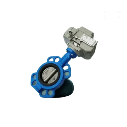
Electric butterfly valves are devices for controlling flow that are typically used in industrial and commercial settings to manage the movement of liquids, gases, and other materials. The working principle is based on a circular disc that is fixed on a rotating shaft, which turns to either allow unrestricted flow, limit it or totally stop it. The electric actuator connected to the valve takes complete control of this operation, resulting in greater efficiency and accuracy. These valves are preferred because of their small size, simple installation, and durability in different types of applications like HVAC, water treatment, and chemical processing.
What is a Butterfly Valve?
An industrial and commercial application of an efficient and versatile device is a butterfly valve that is a flow control device utilizing a rotating disc for starting, regulating, or stopping the fluid flow.
Applications of Electric Butterfly Valves in Industry
Valves with an electric butterfly design are among the most widely used types of valves across different industries because of their ability to operate, accuracy, and automation. Here are five main fields of application for these valves:
1
HVAC Systems
Electric butterfly valves are often used in heating, ventilation, and air conditioning (HVAC) systems. They are responsible for controlling the flow of air or water and, thus, maintaining the desired temperature and optimizing the entire system.
2
Water Treatment Plants
These valves are of paramount importance in water treatment plants, where their operation determines the quality and purity of the water. One of their main features is dependability that leads to a continuous and precise control over e.g. sedimentation and disinfection processes.
3
Power Generation
Electric butterfly valves are used in power generation plants, especially in cooling and steam circulation systems, to support valve control and regulate the fluid flow accurately which in turn contributes to the safe and efficient functioning of turbines, boilers, and other vital equipment.
4
Food and Beverage Industry
Electric butterfly valves are the main choice in the food and beverage sector because of their clean design and smooth operation. They are involved in the processing, mixing, and transfer of liquids such as beverages, syrups, and dairy products throughout the production line.
5
Chemical Processing
Electric butterfly valves are a must-have in the chemical industry for controlling and measuring the flow of different types of chemicals and gases. Their precision handling of corrosive or hazardous substances is an important part of maintaining the plant’s safety and productivity at desired levels.
Types of Electric Butterfly Valves
Electric butterfly valves are available in multiple types, each tailored to specific applications and industrial needs. The following describes the main types of electric butterfly valves and includes their characteristics and advantages:
Wafer Type Electric Butterfly Valve
Description: Wafer-type valves are the most widely used and cheapest design. They are installed in between two flanges and fastened with bolts.
Features:
- Compact, lightweight, easy to install.
- Low-pressure and non-critical applications are recommended.
Use Cases:
- HVAC, water treatment, food processing.
Specifications:
- Usually, pressure ratings are between 150 PSI to 300 PSI.
- The standard materials are stainless steel, ductile iron, and PTFE.
Lug Type Electric Butterfly Valve
Description: Lug type valves allow holes and threads in the valve’s body for the bolts to be attached and the flanges to be disconnected and connected.
Features:
- Reliable alignment and easily maintained.
- Frequent cleaning or servicing is the suitable application.
Use Cases:
- Pharmaceuticals, chemicals, mining.
Specifications:
- The pressure rating range is 150 PSI to 600 PSI.
- The materials usually are carbon steel, bronze, and resilient elastomers.
Flanged Electric Butterfly Valve
Description: This type features a valve body with flanges attached to the pipeline, providing better stability than traditional flanges.
Features:
- Can withstand high-pressure applications.
- Prevent leakage by providing sealing features.
Use Cases:
- Petrochemical companies, oil and gas pipelines, and electricity generation.
Specifications:
- Pressure ratings are often above 600 PSI depending on the design.
- Material selection includes cast iron, stainless steel, and high-performance alloys.
Triple Offset Electric Butterfly Valve
Description: The valves consist of three offsets on the disc and seat, which avoid rubbing and make the seal tight.
Features:
- High durability with no leakage performance.
- Extreme temperature and pressure can be handled.
Use Cases:
- Steam system, high-temperature baking and cryogenic processing.
Specifications:
- Pressure ratings range from 300 to 900 PSI.
- Super duplex stainless steel, titanium, and some special coatings are among the materials used.
Things to Keep in Mind When Choosing Electric Butterfly Valves
- Material Compatibility: Know the fluid or gas the valve will come into contact with, and ensure the valve’s materials can withstand corrosive or abrasive conditions.
- Pressure and Temperature Ratings: Choose a valve with a rating that is high enough to ensure safe and effective operation.
- Actuator Types: Nowadays, electric butterfly valves are installed with high-tech actuators which give the user remote access and automation of the entire system, thus enhancing the efficiency of the system.
Industries can improve control, reliability, and efficiency across processes by selecting the right type of electric butterfly valve that meets specific system requirements.
Tools and Materials for Installation

To carry out the installation of the electric butterfly valve, the following tools and materials will be needed:
- Wrenches and Screwdrivers: To tighten bolts, nuts, and other fasteners.
- Correct Gaskets: To guarantee an efficient sealing between the valve and the pipeline.
- Pipe Cutter or Saw: For changing the length of the pipeline if necessary.
- Measuring Tape: To check the perfect alignment and fit.
- Thread Sealant or Tape: To stop leaks at the joints and connections.
- Safety Gear: That consists of gloves and safety glasses to keep safe during the installation process.
Important: It is advised to use high-quality tools and materials, and to observe the manufacturer’s instructions regarding the installation procedures meticulously.
Essential Tools Required
The effectiveness and safety of the work will, to a large extent, depend on the availability of the right tools to facilitate pipeline installation or maintenance. Below is the presentation of indispensable tools in detail, accompanied by the latest best practices and data:
Best Practice: Before use, each tool must be inspected to ensure it complies with safety regulations and is suitable for your particular project. The said tools, enabled by modern technological advancements and data-driven insights, not only save time but also improve the quality of pipeline installation.
Materials Needed for Installation
A variety of materials are needed to guarantee the pipeline installation’s strength, safety, and efficiency. An updated and thorough list of the most commonly used essential materials for pipeline projects is below:
Pipes
The used materials are steel, PVC, HDPE (High-Density Polyethylene), or copper, depending on the application.
For water pipelines, PVC and HDPE are the most commonly used materials owing to their resistance to corrosion and long-term performance. Under the right conditions, HDPE pipes can remain functional for more than 50 years.
Fittings and Couplings
All the necessary fittings such as elbows, tees, reducers, and adapters are included in the package for connecting pipe sections.
Compression couplings are highly recommended for a quick, leak-proof assembly. Advanced fittings are now fitted with rubber gaskets to enhance the sealing performance.
Pipeline Supports and Anchors
Pipe saddles, hangers, and clamps are some of the supports that help secure pipelines and keep them stable.
Adjustable supports accurately align the pipes and help absorb their expansion due to heat.
Sealing Materials
Thread seal tape (also known as PTFE or Teflon tape) and joint compounds are essential for sealing leaks.
Today’s silicone-based sealants are capable of providing performance that is unbeatable even in high-pressure or high-temperature places.
Insulation Materials
Foam-based or fiberglass insulation can help you reduce heat loss in hot-water pipelines or reduce condensation in cold-water systems.
Many manufacturers comply with environmental standards and provide recyclable, energy-efficient insulation products.
Valves
Ball valves, gate valves, and pressure relief valves are used to manage the flow of liquids.
In a factory setting, the use of advanced smart valves with real-time pressure and flow rate monitoring is a trend.
Fasteners
To hold the pipeline fittings and other components together, stainless steel bolts, nuts, and washers are the most commonly used fasteners.
In addition to anti-corrosion coatings such as zinc plating, the product’s durability is further increased even under harsh conditions.
Protective Coatings and Liners
Pipelines coated on the outside with epoxy or polyethylene sheaths have virtually no risk of rust, abrasion, or chemical exposure.
Applying internal linings, such as cement mortars, strengthens pipelines used for the transportation of drinking water.
Gaskets
A watertight seal is provided at the pipe joints by using rubber or elastomeric gaskets.
Upgraded composite gaskets offer more heat resistance and better chemical resistance than their predecessors.
Grouting and Backfill Materials
Materials used for backfilling trenches include sand, gravel, and controlled low-strength material (CLSM) and provide structural support.
Research indicates that the use of CLSM can cut project costs by as much as 30% due to its shorter setting time compared to conventional materials.
Critical Note: The quality of materials sourced from reputable manufacturers is a key factor in the positive outcome of a pipeline installation. Furthermore, it is important to check the project specifications, environmental issues, and regulatory requirements before selecting materials to guarantee compliance. The application of contemporary material solutions that are guided by data can increase the durability, safety, and effectiveness of the pipeline systems.
Choosing the Right Valve Actuator
When selecting the appropriate valve actuator, I focus on a few key aspects. To begin with, the valve type, along with the required actuation method—manual, electric, pneumatic, or hydraulic—is the first issue I look into. After that, I take torque and operational requirements into account to ensure the actuator can withstand the load. Besides that, I consider the environmental factors, including temperature, humidity and the possibility of being in contact with corrosive materials, in order to make the right choice of a durable and reliable actuator. And lastly, I will verify control system compatibility and ensure the actuator meets project specifications and industry standards.
Step-by-Step Installation Process

1
Preparation and Planning
First of all, among the preparations prior to the installation steps, availability of appropriate tools and resources is a must. The most common tools consist of, among others, torque tools, wrenches, screwdrivers, and any other equipment specified by the manufacturer as suitable to the job. Make sure to check the actuator specs twice, for instance, temperature tolerance, torque, and existing system compatibility. Moreover, calibration tools for most pneumatic and electric actuators are being mentioned in recent guidelines by manufacturers as a necessity to their alignment with the desired operational outputs. Consult the manufacturer’s manual for any warnings specific to your actuator model.
2
Inspect the Mounting Surface
The mounting surface or flange must be clean, level, and clear of any debris. Incorrect alignment can lead to operational errors or mechanical stress, so it is essential to obtain the proper alignment. Current statistics show that up to 15% of efficiency is lost due to misaligned actuators, leading to increased wear and tear over time. A leveling tool is a good option for checking alignment, and if necessary, you can make changes to the surface or the mounting points.
3
Attach the Actuator
The actuator should be appropriately positioned and carefully mounted on the valve or other controlled equipment. For actuators with a threaded or bolt-mounted setup, use the correct fasteners to secure the actuator, following the manufacturer’s torque specifications. The research asserts that over-tightening bolts may cause them to fracture due to accumulated stress over time, so it is better to tighten them evenly and carefully.
4
Connect Control Systems
Connect or wire the actuator to its control system. For electric actuators, connect the power supply and communication lines, ensuring the voltage ratings are met. Pneumatic actuators should be appropriately connected to the air supply, and the pressure levels should be set according to the actuator’s specifications. As recommended by industry sources, testing for leaks is an absolute must once all connections are made, as an untreated pneumatic leak can result in an efficiency loss of up to 20%.
5
Configure and Test
After installing the actuator, connecting it, and calibrating it to the control system, the next step is to configure it. The setting of limits, sensitivity, or torque outputs can be done using manufacturer-recommended software or diagnostic tools. The industry also supports conducting a series of functional tests to ensure that the actuator is entirely operational. Check for the actuator’s smooth control signals, operating under specified torque limits, and meeting accuracy requirements during load conditions.
6
Final Inspection and Maintenance Setup
Right before the end of the installation, perform a thorough inspection, including all connections and fasteners. Check compliance with manufacturers’ guidelines for every step by cross-referencing them. In addition, implement scheduled maintenance programs to increase the actuator’s service life. Maintenance intervals depend on operating conditions, but the common advice is to inspect actuators every 6–12 months under normal operating conditions. Keep records of all installation and calibration data for later use.
Success Guarantee: Upon completion of these steps, the actuator will function perfectly with no impact on the system’s efficiency or reliability.
Preparing the Installation Site
The proper preparation of the installation site significantly impacts the actuator’s performance and lifespan. Start by examining the mounting surface, which should be perfect for the installation —free of dirt, even, and without any remnants —since rough or dirty surfaces could block the actuator’s alignment and stability. A spirit level should be used to verify that the surface is leveled correctly, since even a very slight slope can cause mechanical strain over time. Besides, it is essential to verify that the actuator’s surrounding environment meets the operational requirements imposed by the actuator, such as temperature limits (often between -4°F/-20°C and 122°F/50°C for standard actuators) and protection against excessive moisture, dust, and chemical exposure.
Checking the compatibility between actuator’s mounting bracket and fasteners and the equipment or system to which the actuator will be mounted is also mandatory. Brackets should have load rating to withstand the load under consideration, taking into account both static and dynamic forces. For instance, a heavy-duty actuator used in automation applications might require brackets capable of supporting a load of up to 10,000 N.
Make sure and have the electrical and pneumatic connections, if any, well-prepared. Inspect wiring conduits and tubing for continuous routes without kinks, stresses, or possible pinch points, and verify their functionality before connecting them to the actuator. Electrical cables should have proper environmental ratings that comply with applicable guidelines when used in areas where harsh conditions are expected; for instance, IP67 or higher for electrical cables used in cabling applications that meet the environmental requirements.
Finally, it is necessary to have clear areas around the actuator for routine inspection and maintenance. At least 6-10 inches of space must be allowed around the unit to enable easy access without dismantling the system. A well-done installation site will be the most supportive of the actuator to stand up to the trials of time in the aspects of alignment, protection, and performance.
Installing the Electric Butterfly Valve
The proper installation of an electric butterfly valve is very important for the efficient functioning of the plant, the short downtime and the long life of the plant. The following are the detailed steps and instructions to be followed during the installation process:
Inspection and Preparation
- Before starting the installation work, inspect the valve and actuator for any damage or faults. Also, make sure all parts, such as seals, fasteners, and gaskets, are in good working order.
- Check that the valve’s specifications, including size, pressure rating, and material compatibility, are in accordance with the application requirements. Standard industry sizes range from 2 inches to 48 inches, depending on the pipeline width.
Cleaning of the Pipeline
- Remove all dirt, rust, and other debris from the pipeline that might affect the valve’s operation, ensuring a thorough cleaning.
- Check that the flanges to be joined are aligned, free of burrs or scratches, and prepared so there will be no leaks at the installation point.
Mounting the Valve
The butterfly valve should be positioned in between the pipeline flanges and then firmly fastened with proper bolts. It is advisable to use a torque wrench to ensure the bolts are tightened uniformly, maintaining proper alignment and tension. Refer to the manufacturer’s torque specifications for practice to avoid over-torquing or under-torquing. The most common values range from 50 to 150 Nm, depending on the valve’s size and materials.
Installation of the Electric Actuator
- The actuator should be synchronized with the valve stem and mounting flange. The actuator should be securely attached to the valve using the appropriate hardware provided with the actuator. The actuator should be certified by the industry standards, such as ISO 5211, which specifies the mounting compatibility.
- The actuator’s electrical wiring should be connected following the specific wiring diagram. The power supply should be in line with the actuator’s voltage and amperage requirements (usually 24V DC, 110V AC, or 230V AC). To extend the equipment’s lifespan in a weather-unfriendly environment or at very high temperatures, use waterproof, heat-resistant cables.
Testing and Calibration
- After the installation, check the alignment by opening and closing the valve a few times by manually operating the actuator. Watch for any unnecessary wear on the resistance or misalignment during the process.
- The electrical operational test should include making the actuator active and cycling the valve. The actuator’s open and closed limits may be set according to the manufacturer’s recommendations to ensure the most accurate control.
Final Inspection and Maintenance Tips
- Check for leaks or loose connections in the hardware. Use sealant on the flanges if needed to make them leakproof and reduce the risk of leaks.
- Record baseline operating intervals (e.g., torque settings, valve positions) so that troubleshooting in the future will be made easier. In industrial settings, regular inspections and maintenance every 6-12 months are recommended for wear and tear.
Installation Success: By adhering to these steps, the installation of the electric butterfly valve would be correct and it would be a reliable part of the system. For extreme conditions or dangerous applications, consult the manufacturer’s specific guidelines to ensure compliance with safety norms and operational needs.
Connecting the Actuator
The proper connection of the actuator to the electric butterfly valve is vital for ensuring smooth, efficient operation. Here are the comprehensive steps along with the important points to take into account:
Check Compatibility
Firstly, it is necessary to confirm that the actuator is suitable for the butterfly valve in terms of torque requirements, operational voltage, and control signal type (e.g., 4-20mA, 0-10V, or ON/OFF). Also, check with the manufacturer’s literature for the most recommended combinations of valves and actuators.
Actuator Mounting
- If the ISO 5211 standard applies, position the actuator’s mounting flange in line with the valve’s mounting flange.
- Make sure the valve’s drive shaft is adequately coupled to the actuator’s coupling or drive socket.
- Fasten the actuator mounting bolts to the specified manufacturer torque and ensure they are tight.
Wiring the Electricity
- The actuator should be connected to the power supply and control system. Electric actuators usually come in voltages like 24V DC, 110V AC and 230V AC. Make sure the voltage matches the actuator’s requirements.
- Carefully follow the wiring diagram that comes with the actuator and make sure the control signal cables (for instance, open/close position feedback and control) are correctly connected.
- In the industrial setting, cables must be properly rated and insulated to withstand the environment, and wiring should be secured with cable glands to prevent loosening or damage.
Setting Parameters and Calibration
- Today’s actuators are often equipped with digital settings for stroke limits, travel time, and control signal feedback. Either the actuator’s user interface or software tools are to be used to set these parameters.
- To test the actuator, run it through the open and close positions. Make sure the valve moves through its full range without over-traveling or becoming too stressed.
Testing and Commissioning
- A functional test should be conducted to determine whether the actuator responds to the control signals. If applicable, test the emergency modes, such as manual override or fail-safe positions.
- Determine the response times and ensure the actuator provides sufficient torque for valve operation under expected system conditions.
Data on Selecting Electric Butterfly Valve Actuator Torque
The general rule is to select an actuator that provides 20% more torque than the valve’s maximum operating torque, accounting for factors such as fluid viscosity and system pressure. To illustrate, if the butterfly valve requires 50 Nm for operation, the actuator torque should be rated at least 60 Nm to ensure exceptional performance without overloading.
Conclusion
The proper connection and configuration of the actuator lead to greater accuracy, reduced mechanical wear, and improved service life. For sophisticated applications, the use of actuators with smart capabilities, such as diagnostics and real-time performance monitoring, is recommended to make the most of the system. Always consult the latest manufacturer-specific information for exact installation and tuning recommendations.
Common Mistakes to Avoid During Installation
Avoiding common installation mistakes is crucial for ensuring optimal performance and longevity of your electric butterfly valve system. Here are the most critical errors to watch out for:
❌ Incorrect Wiring Connections
One of the major mistakes in the actuator installation process is incorrect wiring. One of the induced problems by misconnected wires is the erratic behavior of the actuator and even the permanent damage to the actuator and the connected components. Always refer to the wiring diagrams and follow the manufacturer’s specific guidelines.
❌ Failure to Check Voltage Specifications
A common mistake is to use an incorrect voltage supply. Supplying either too high or too low voltage can create functional problems, and the actuator’s life will be cut short or there is a risk of overheating the crucial parts. Always check the expected voltage range before connecting to the power supply.
❌ Neglecting Calibration
After installation, the actuators will usually need fine calibration done in order to be able to work with the system at its best. If you miss this step, you will get the actuator to make incorrect motions, reduced accuracy, or even higher energy consumption. Make good use of the manufacturer tools and instructions to do the present calibration of the actuator.
❌ Improper Mounting
An actuator mounted without proper alignment or stability will soon cause problems. Increased wear, misaligned movements, and hence overall inefficiency will be the result of such a practice. Check that the mounting brackets and hardware are secure and completely aligned with the intended load or the system.
❌ Overlooking Environmental Conditions
Dismissing environmental factors such as temperature, humidity, or exposure to corrosive substances might have a significant negative impact on the actuator’s performance. Always use actuators that have been rated as per the specific environmental conditions and also utilize proper sealing where necessary.
Incorrect Sizing of Valves
Incorrect sizing of valves can bring about a series of operation difficulties like inefficiency, system shutdown, and maintenance. Proper sizing is of paramount importance for optimal performance and functionality. Discussed below are five main problems due to bad sizing of valves:
Flow Rate Mismatch
The system’s flow demand when it is either too large or too small for a valve will result in poor regulation, cavitation, or even pressure drops. For instance, an oversized valve could function at a throttled position which would then cut its life expectancy.
Pressure Drop Issues
Mismatched valve sizes can cause pressure instability in the system. While an overly tight valve will increase pressure drop area, an oversized one may be unable to hold the necessary pressure.
Erratic Control
Valves of the wrong sizes can sometimes lead to poorly controlled systems, resulting in erratic performance. This very malfunction can be a headache in processes that require minute control, for instance, chemical dosing.
Energy Inefficiency
Improperly sized valves can lead to higher energy consumption in the system. For example, a small valve may consume a lot of energy just to keep the flow going, while a large one may lose energy during partial closure.
Premature Wear and Tear
Valves that are constantly working the wrong way because they are too small or too large are very likely to wear out. This eventually leads to frequent repairs and downtime, thereby increasing operational costs.
Prevention Tip: To determine the proper valve size, a thorough analysis of the system requirements —including flow rate, pressure range, and environmental conditions —must be conducted. When these factors are taken into account during the selection process, many of these issues can be easily avoided.
Improper Wiring of the Actuator
Incorrect actuator wiring can result in a severe malfunction and thus very high performance inefficiencies. So it is vital to have the correct wiring configuration for the actuator’s operation, since wiring errors can jam the system, damage parts, and even pose a safety risk. The following are five critical problems that can happen with improper wiring:
⚠️ Reversed Polarity
Wiring the polarity backwards might cause the actuator to move in the opposite direction or not work at all. So this would cause a disturbance across the whole system and would require immediate steps to correct the situation.
⚠️ Loose Connections
Loose or not well-secured connections might result in the actuator working sometimes and not also losing the signal. This problem might cause an unreliable system performance and thus frequent operational delays.
⚠️ Incorrect Voltage Supply
Feeding the actuator with a voltage outside the specified range can cause its internal components to heat up or be destroyed, leading to eventual failure.
⚠️ Crossed Signals
Miswiring that mingles the control and power signals can result in the actuator acting unsystematically, such as unexpected operation or an inability to respond properly to system commands.
⚠️ Insufficient Grounding
Improper grounding can create electrical noise, accelerate actuator wear, and pose safety risks, including electrical shocks or system damage from surges.
Critical Reminder: All these problems highlight the need for proper wiring methods and careful double-checking of connections before powering the equipment. Adhering to installation guidelines and performing routine maintenance can resolve these issues and help keep the system running at its best.
Neglecting to Test for Leaks
Leak testing is a vital yet often neglected step in system installation and repair. The presence of leaks can cause a variety of problems such as wste of energy, lower efficiency, and ultimately damage to the equipment. Recent studies in the industry claim that leaks in compressed air systems can account for 30% of the total energy lost, thus, leading to a significant hike in operational costs. In the same manner, if fluid systems are not properly tested, they can suffer from pressure fluctuations, contamination, and even environmental hazards such as spills.
This situation calls for the application of very effective methods of leak detection such as the use of electronic leak detectors, tests with soapy water, or the use of ultrasonic technologies. Moreover, conducting regular system audits can identify leakage points and help maintain the system’s integrity. Data from maintenance studies show that industries which have adopted regular leak testing programs have been able to cut down their operational costs by as much as 20% and at the same time, their equipment has been lasting longer. Following testing procedures diligently and using the latest detection technologies can significantly reduce the risks posed by ignoring system leaks.
💡 Key Statistics
- 30% energy loss from untreated leaks in compressed air systems
- 20% reduction in operational costs with regular leak testing
- Significantly extended equipment lifespan through preventive testing
Maintenance Tips for Electric Butterfly Valves
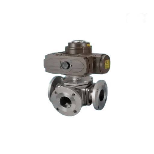
Proper maintenance is essential for ensuring the longevity and optimal performance of your electric butterfly valves. Follow these expert-recommended maintenance practices:
🔧 Regular Lubrication of Moving Parts
All moving parts, such as the stem and actuator components, must be properly lubricated to prevent wear and tear. Researchers estimate that the operational life of well-lubricated valves is 15% longer than that of poorly maintained ones.
🔍 Periodic Inspection for Corrosion
The valve body and internal parts should be checked for corrosion, especially in areas with high moisture or corrosive substances. If corrosion is not addressed, it can lead to poor performance and even system failures.
🔩 Tightening and Adjustment of Fasteners
Check if bolts, screws, and fasteners are tight. Loose connections can result in misalignment or leaks, which in turn affect the valve’s efficiency and safety. Tighter fittings for these components can reduce operational downtime caused by improper fit by up to 10%.
✅ Testing for Seal Integrity
Perform regular pressure and leak tests to verify the sealing ability of the seals and gaskets. Defective seals can affect the precision of fluid control and allow particles to enter the system.
🧹 Ensuring a Clean Operating Environment
Keep the area around the valve clean and free of debris so that valve movement and actuator performance are not affected. Periodic cleaning of valves can increase operating efficiency by 8%-12%, particularly in dust-prone areas.
Routine Inspection and Cleaning
Routine inspection and cleaning of industrial valves are essential activities that guarantee peak performance and even extended service life. Recent studies indicate that faulty valve maintenance can reduce efficiency by up to 20% and, at the same time, increase operational costs and decline system productivity.
📋 Inspection Checklist:
Visual Inspection:
- Look for any visible signs of wear, corrosion, or leakage.
- The valve body and actuator should be inspected for any cracks, dents, and loose fittings.
Seal and Gasket Condition:
- Check seals and gaskets for dry rot, tears, or compression damage.
- Damaged seals should be replaced to maintain the system’s integrity.
Operational Test:
- Operate the valve to check whether it moves and functions properly.
- Document any resistance, noise, or delay that is not usual and may signal internal blocking or mechanical damage.
🧼 Cleaning Recommendations:
Surface Cleaning:
- Get rid of all dirt, grease, and debris from the outside of the valve using non-abrasive cleaners and cloths.
- Steer clear of strong chemicals that may corrode metal surfaces or ruin rubber parts.
Internal Cleaning:
- Take apart valves whenever feasible to clean the inside of the valve and remove any sediment or scale that has built up.
- In water systems, flushing pipelines can help reduce scale and debris buildup.
Environment Management:
- Indoor valves located in industrial zones should be dust-proof.
- Valves should be fitted with protective covers to prevent excess airborne particulates.
✨ Benefits of Routine Cleaning:
- Research and industry standards suggest that cleaning valves regularly can lead up to 15% efficiency improvement.
- It reduces the occurrence of unexpected downtime caused by blockages or malfunctions.
- Correct maintenance adds years to the valves’ lifespan, thereby reducing the frequency and costs of replacement by nearly 25%.
Best Practice: By implementing an exhaustive inspection and cleaning schedule, industries can keep their valves running efficiently even in the harshest environments, leading to smoother operations and increased system reliability.
Troubleshooting Common Issues
Valves are an important part of any system and, when they are being worked on, there are some frequent problems that could pop up and cause the system performance to be affected. However, if the issues are recognized in time and the correct solutions are applied, severe disruptions to operations can be avoided. Listed below are five typical valve issues accompanied by their descriptions and solutions:
🔴 Leakage
Details: Leakage occurs when seals are worn out, installation is improper, or corrosion occurs inside the valve. It usually results in wasted energy and lower efficiency.
Data: Research has shown that up to 20% of energy could be wasted if leaking valves are not taken care of.
Solution: Make it a point to regularly check the seals, replace any damaged parts, and ensure the fit is correct during installation.
🟡 Sticking or Jammed Valves
Details: Debris accumulation, rusting, or inadequate lubrication may cause valves to stick or jam which will prevent them from operating smoothly.
Data: Jamming accounts for almost 30% of valve failures.
Solution: Regularly clean the valves and use the right type and amount of lubricant to prevent debris from building up and to allow smooth movement.
🔵 Pressure Imbalance
Details: A clogged valve path can lead to faulty pressure control which results in pressure imbalances and consequently, uneven flow rates.
Data: 10% of the system’s performance efficiency can be lost when the system is affected by pressure issues.
Solution: Identify the blockages and adjust the pressure settings to meet the system’s requirements.
🟣 Corrosion and Material Degradation
Details: Harsh chemicals and extreme temperatures are the main factors contributing to valve corrosion and material weakness, especially when the exposure is prolonged.
Data: Corrosion causes 40% of valve replacements in industrial applications.
Solution: Choose corrosion-resistant materials and apply coatings to protect the valves and extend their lifespan.
🟢 Vibration and Noise
Details: Loose parts, poor installation, or turbulent flow in the system are the main causes of excessive vibration or noise.
Data: If vibrations are not addressed, the valve’s lifetime could be cut short by as much as 35%.
Solution: Find and tighten loose parts, ensure the valves are firmly installed, and look for any abnormal flow dynamics.
Key Takeaway: Industries can increase production and reduce the risk of operational failures if the problems mentioned above are recognized and resolved in time.
Expert Recommendations for Longevity
To guarantee that industrial valves and systems will last for a long time, consider the following expert advice:
References
Transient Effects on Dynamic Torque for Butterfly Valves
This study explores the operational dynamics of butterfly valves, including installation impacts.
A Numerical Study of the Flow through a Safety Butterfly Valve in a Hydro-Electric Power Scheme
This paper examines the flow and torque characteristics of butterfly valves in hydro-electric systems.
Structural Design and FEM Analysis of Large Butterfly Valve: A Review
This review focuses on the structural design and installation considerations for large butterfly valves in hydro-electric setups.
Frequently Asked Questions (FAQ)
❓ What is an electric butterfly valve and how does it function?
An electric butterfly valve is essentially a flow control instrument that is operated by an electric actuator which can open and close the valve plate thus, letting or stopping the fluid flow through the pipeline. This valve is usually a quarter-turn; hence, it is very fast and efficient in regulating the flow rate. Electric butterfly valves are very popular in a range of industrial processes because they can last long and are easy to automate.
❓ How do I install a butterfly valve?
To install a butterfly valve, a series of steps need to be appropriately followed. First, make sure the pipeline is ready for installation and that the pipe flanges are in line. Depending on the kind of butterfly valve you have, you might need a flange butterfly valve or a wafer type butterfly valve. Position the valve carefully between the flanges and make sure the valve seat is aligned correctly. Bolt the valve in place and check for any welding slag or dirt that could inhibit its movement. Next, hook up the actuator to the valve body and verify the valve stem’s alignment for accurate installation.
❓ What are the main components of an electric butterfly valve?
The main parts that make up an electric butterfly valve are the valve body, valve disc, actuator, valve stem, and valve seat. The valve body is the housing for the interior valve parts and it also provides the physical strength support, whereas the valve disc is the element that either cuts off or opens the fluid passage to regulate the flow. The electrically powered actuator rotates the valve disc in the desired direction. The valve stem is the connector between the actuator and the valve disc while the valve seat seals the valve securely when it is closed.
❓ What types of electric butterfly valves are available?
There exist quite a few electric butterfly valves types, like single-offset, double-offset, and triple-offset butterfly valves. The performance of each type is unique, and therefore, they fit different applications. For example, triple-offset butterfly valves are suitable for high-pressure and high-temperature applications; in contrast, wafer-type and lug-type valves are generally used for standard flow control applications. The right type of electric valve selection is key to realizing the desired performance and durability of the system.
❓ How does an actuator work in an electric butterfly valve?
The actuator in an electric butterfly valve converts electrical energy into mechanical motion that opens and closes the valve plate. Upon receipt of the signal, the actuator rotates the valve stem, causing the valve plate to turn through 90 degrees and either permitting or blocking the flow. Such an automated process increases productivity and reduces human intervention, thereby making electric butterfly valves very suitable for smart computerized systems.
❓ Can I manually operate an electric butterfly valve?
Sure enough, in many cases, electric butterfly valves are equipped with a manual override that allows manual control during power outages or during maintenance. Normally this function involves a handwheel or lever that is operated to open or close the valve when it is called upon. Nevertheless, it is crucial to ensure that manual operation does not damage the actuator or any valve components.
❓ What are the advantages of using electric butterfly valves in automation?
Electric butterfly valves offer many benefits in automated systems, including very accurate flow regulation, instant response, and minimal maintenance requirements. Their ability to be coupled with control systems allows flow rates to be monitored and adjusted instantly, making them excellent for energy-intensive processes. Moreover, compared to other types of valves, electric butterfly valves have fewer moving parts, which can reduce wear and tear over time.
❓ What should I consider when selecting an electric butterfly valve?
Various factors, such as flow rate, the medium’s temperature and pressure, and the specific application and processing requirements, should be considered when selecting an electric butterfly valve. It is not only crucial to choose the right size and type of the valve but also whether it is a flange butterfly valve, wafer type, or one of the others. Furthermore, ensure the actuator’s parameters align with the system’s performance requirements to ensure proper functioning.