

2-Way vs 3-Way Fan Coil Valve: Which Should You Choose?
Marcus, a consulting engineer in Dubai, once specified 3-way diverting valves for a 12-storey office retrofit because that was what the original constant-flow plant used. The client had already installed variable-speed pumps and differential pressure controls. Six months after handover, the energy audit showed the pumps were still running at 85% speed at 30% cooling load.
The 3-way valves were bypassing water around satisfied coils while the VFDs hunted for a flow reduction that never came. The building missed its LEED energy target by 12%. The fix was simple in hindsight: replace the 3-way valves with 2-way modulating valves and let the pumps slow down with demand.
If you have ever stood in front of a fan coil unit specification and asked whether a 2-way or 3-way valve is the right choice, you’re not alone. The question sounds like a component decision, but it’s really a system-design decision. This guide compares 2-way and 3-way fan coil valves on flow behavior, hydronic fit, energy impact, sizing, and control integration so you can specify the right valve for your project the first time.
You will learn how each valve works, when to use it, what it means for pump energy, and how to avoid the four mistakes that turn a good valve selection into a commissioning headache.
Ready to see how the right valve configuration fits your system? Explore Black Ant’s DN15-DN25 fan coil control valve range →
What Is the Difference Between a 2-Way and 3-Way Fan Coil Valve?

A 2-way fan coil valve has one inlet and one outlet. It opens to allow water through the coil and closes to stop it. A 3-way fan coil valve has three ports, A, B, and a common AB port, and diverts water either through the coil or through a bypass while keeping total system flow nearly constant.
The core distinction is not the number of pipes in the building. It is whether the hydronic system is designed for variable flow or constant flow. Match the valve to the flow strategy and the system runs efficiently. Match it wrong and even the best actuator can’t fix the energy waste or control instability that follows.
2-Way Valve: One Inlet, One Outlet
A 2-way valve acts like a variable resistance in the line to the fan coil. When the room thermostat calls for heating or cooling, the actuator opens the valve. When the setpoint is reached, the valve closes and flow through the coil stops. This makes the branch flow variable, which is exactly what variable-speed pumps are designed to exploit.
In most fan coil installations, the 2-way valve sits on the return side of the coil. It can be normally open (NO), valve opens when power is lost, useful for freeze protection in heating coils, or normally closed (NC), valve closes when power is lost, common in cooling-only applications.
3-Way Valve: A, B, and Common AB Ports
A 3-way valve has two inlet/outlet paths in addition to the common port. In HVAC fan coil applications it usually functions as a diverting valve on the coil outlet: water returns either through the coil path (port A) or through a bypass path (port B). When the coil is satisfied, flow is redirected around the coil instead of being stopped.
Less commonly, a 3-way valve is used as a mixing valve to blend hot and cold water streams to a controlled supply temperature. Mixing configurations are more typical in boiler bypass loops or radiant panel applications than in standard fan coils. To learn more about the Fan Coil 2 Pipe 4 Pipe System: HVAC Selection Guide, please click to refer to our accompanying guide.
Mixing vs Diverting Configurations
| Configuration | Port Function | Typical HVAC Use |
|---|---|---|
| Mixing | Two inlets (A, B) blend to one outlet (AB) | Boiler bypass, radiant panel temperature control |
| Diverting | One inlet (AB) splits to two outlets (A, B) | Fan coil bypass, chiller/boiler constant-flow protection |
Most fan coil 3-way valves are diverting. The bypass leg returns water directly to the system, preserving flow in the primary loop.
How a 2-Way Fan Coil Valve Works
In a 2-way valve, the actuator positions a plug, ball, or disc between fully open and fully closed. The control signal determines the opening:
- On/off (2-position) control: valve is either fully open or fully closed. Simple and low-cost, but temperature control is coarse.
- Modulating control: valve stops at any intermediate position. A 0–10 V or 4–20 mA signal from the thermostat or BMS positions the valve proportionally to load.
Variable Flow Control Through the Coil
When a 2-way valve modulates toward closed, flow through the fan coil drops. If every fan coil in the building does this simultaneously during part-load conditions, the total system flow falls. A variable-speed pump with a differential pressure sensor slows down to match, and pumping energy drops with the cube of the flow reduction.
This is why 2-way valves are the default choice for modern energy-efficient buildings. They turn reduced demand at the terminal units into reduced pumping energy at the central plant.
Normally Open vs Normally Closed Operation
| Fail-Safe Position | Behavior When Power Lost | Typical Application |
|---|---|---|
| Normally open (NO) | Valve opens, allowing flow through coil | Heating coils in cold climates; freeze protection |
| Normally closed (NC) | Valve closes, stopping coil flow | Cooling-only fan coils; energy savings priority |
Selection depends on safety. A NO valve protects against frozen coils by allowing flow if the actuator fails. An NC valve protects against overheating or unnecessary cooling when control power is lost.
Typical Piping in 2-Pipe and 4-Pipe Systems
- 2-pipe system: one 2-way valve per fan coil, because the coil handles either chilled or hot water seasonally.
- 4-pipe system: two 2-way valves per fan coil, one for the chilled water coil and one for the hot water coil. Each coil is controlled independently.
If every fan coil in a branch uses 2-way valves, the design must include either a differential pressure bypass valve at the end of the branch or a variable-speed pump with a minimum-flow protection strategy. Otherwise the pump can dead-head when all valves close.
How a 3-Way Fan Coil Valve Works
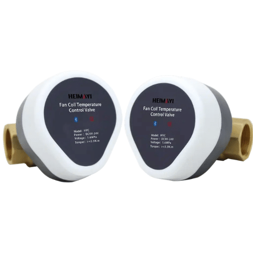
A 3-way fan coil valve maintains total flow while diverting it away from the coil when demand drops. The actuator moves an internal element that changes the ratio of flow between the coil port and the bypass port.
Constant Total Flow With Bypass Path
When the thermostat calls for full heating or cooling, the 3-way valve directs all return water through the coil. As the room approaches setpoint, the valve gradually shifts flow to the bypass leg. Total flow in the branch remains nearly the same, so a constant-speed pump continues to operate at a stable point.
This behavior makes 3-way valves essential in constant-flow systems where equipment, some older chillers, boilers, or heat exchangers, requires a minimum flow rate to operate safely and efficiently.
Diverting vs Mixing Application in FCUs
In fan coils, the 3-way valve is almost always a diverting valve piped on the coil outlet:
- Port AB connects to the coil outlet.
- Port A connects to the system return.
- Port B connects to the bypass line that joins the return.
When the coil is off, water flows AB → B. When the coil is on, water flows AB → A. The common mistake is to pipe the bypass as a dead-leg rather than connecting it back to the return; this traps stagnant water and creates temperature control problems.
Typical Piping and Bypass Arrangement
The bypass leg should have roughly the same pressure drop as the coil at design flow. If the bypass is too restrictive, flow will preferentially go through the coil even when the valve commands bypass. If the bypass is too free, the coil may be starved when the valve calls for coil flow.
For this reason, 3-way valves are often selected with a bypass line sized to match the coil pressure drop, or supplied as a packaged valve-and-bypass assembly.
2-Way vs 3-Way Fan Coil Valve Comparison Table
| Feature | 2-Way Fan Coil Valve | 3-Way Fan Coil Valve |
|---|---|---|
| Ports | 1 inlet, 1 outlet | 3 ports: A, B, AB |
| Flow behavior | Variable flow through coil | Constant total flow; coil or bypass |
| System type | Variable-flow systems | Constant-flow systems |
| Pump compatibility | Variable-speed (VFD) pumps | Constant-speed pumps |
| Energy efficiency | Higher at part load | Constant energy use |
| Piping complexity | Simpler | Requires bypass leg |
| Common control | On/off or modulating | On/off or modulating |
| Best for | Modern 2-pipe/4-pipe energy-efficient designs | Older systems, equipment needing minimum flow |
| PICV compatibility | Yes, ideal for pressure-independent control | Less common |
Want the full sizing logic behind this comparison? See our step-by-step fan coil valve sizing guide for Kvs, Cv, and authority calculations.
When to Choose a 2-Way Fan Coil Valve

Variable-Flow Systems With VFD Pumps
If the building uses variable-speed pumps and differential pressure control, 2-way valves are the logical choice. They allow the pump to slow down as load falls, capturing the full energy benefit of variable flow.
Energy-Efficient Modern Buildings
Projects targeting green certifications, low operating cost, or utility rebate programs generally favor 2-way modulating valves. The combination of precise zone control and variable-speed pumping is the standard for new commercial construction.
2-Pipe and 4-Pipe Designs With Differential Pressure Control
In a 2-pipe system, one 2-way valve per coil is sufficient. In a 4-pipe system, two 2-way valves per unit allow independent heating and cooling control. Both configurations work provided the plant includes differential pressure control or a bypass strategy.
Integration With PICVs and BEMS
A pressure independent control valve (PICV) is essentially a 2-way characterized control valve with an integrated differential pressure regulator. It maintains design flow to the coil regardless of pressure fluctuations elsewhere in the system. PICVs are almost always 2-way and are ideal for large fan coil networks where manual balancing would be impractical.
When to Choose a 3-Way Fan Coil Valve
Constant-Flow Systems With Fixed-Speed Pumps
If the project uses constant-speed pumps and the plant is not designed for variable flow, 3-way valves maintain stable total flow. They prevent pump dead-heading and protect equipment that needs continuous circulation.
Equipment Requiring Minimum Flow
Some older chillers, boilers, and heat exchangers have minimum flow requirements. In these systems, shutting off branch flow with 2-way valves can cause temperature stratification, low-flow alarms, or equipment damage. A 3-way bypass preserves the required flow.
Bypass and Mixing Applications
3-way valves are used in primary/secondary decoupled loops, boiler bypass circuits, and mixing applications where the goal is temperature blending rather than isolation.
Retrofit Projects Where Flow Must Be Preserved
When retrofitting controls into an existing constant-flow building, switching to 2-way valves may require pump and control upgrades that are not in the budget. Keeping 3-way valves avoids disturbing the hydraulic profile of the existing system.
Energy Impact: Why Valve Choice Affects Pumping Power
Elena, a facility manager in Singapore, inherited a 20-year-old hotel with 3-way valves on every fan coil and fixed-speed primary pumps. Her cooling bills were flat regardless of occupancy. After a phased upgrade to 2-way modulating valves, VFD pumps, and a building energy management system, she cut pumping energy by 44% in the first year. The guest comfort scores also improved because the valves modulated instead of cycling fully open and closed.
Variable Flow and the Pump Affinity Laws
Pump power is proportional to the cube of flow. Reducing flow to 50% of design theoretically reduces pump power to 12.5% of full-load power, an 87.5% reduction. Even after real-world inefficiencies, variable-speed pumping with 2-way modulating valves can cut pumping energy by 30–50% compared to constant-flow designs.
Quantified Savings Potential of 2-Way + VFD Systems
ASHRAE 90.1 requires many pump systems over 5 hp to reduce power to 30% at 50% flow. Real-world variable-speed systems with 2-way valves and remote differential pressure sensors have demonstrated pumping energy savings of up to 65% in part-load operation.
Why 3-Way Valves Maintain Constant Energy Use
A 3-way valve bypasses water around the coil instead of stopping it. The pump still moves nearly the same volume of water, so pumping energy remains high even when the building needs little heating or cooling. The trade-off is hydraulic simplicity and equipment protection.
Sizing Implications for 2-Way vs 3-Way Valves

Sizing a fan coil valve isn’t about matching the pipe diameter. It’s about matching the flow coefficient (Kvs or Cv) to the coil load, water temperature difference, and available pressure drop.
Authority Considerations for 2-Way Valves
Valve authority is the ratio of pressure drop across the fully open valve to the total pressure drop across the valve plus coil:
Authority=ΔPvalveΔPvalve+ΔPcoilAuthority=ΔPvalve+ΔPcoilΔPvalve
For stable proportional control, authority should be between 0.25 and 0.5. Below 0.25, the valve is oversized and the actuator hunts. Above 0.5, the valve wastes pump energy and may generate noise.
A practical rule of thumb from Johnson Controls sizing guidance is to size the modulating valve so its pressure drop is 1–2 times the coil pressure drop.
Bypass Pressure Drop for 3-Way Valves
For 3-way diverting valves, the bypass leg must be considered part of the hydraulic design. If the bypass pressure drop is much lower than the coil pressure drop, the valve will not divert flow effectively when commanded. Ideally, the bypass is sized to match the coil pressure drop at design flow.
Kvs Selection and Common DN15–DN25 Ranges
| Valve Size | Typical Kvs Range | Chilled Water Capacity (ΔT = 5 K) | Hot Water Capacity (ΔT = 10 K) |
|---|---|---|---|
| DN15 (½”) | 0.63 – 2.5 | 1.5 – 6 kW | 3 – 12 kW |
| DN20 (¾”) | 1.6 – 4.0 | 4 – 10 kW | 8 – 20 kW |
| DN25 (1″) | 2.5 – 6.3 | 6 – 16 kW | 12 – 32 kW |
For a detailed step-by-step sizing procedure, see our fan coil valve sizing guide.
Actuator and Control Signal Considerations
The valve body determines the flow path. The actuator determines how precisely and quickly the valve responds.
On/Off (2-Position) vs Modulating Control
- On/off control is the simplest and least expensive option. It works for basic comfort control but causes wider temperature swings.
- Modulating control provides smoother temperature regulation and is essential for energy-efficient variable-flow systems.
0–10V, 4–20mA, and 3-Point Floating Signals
| Signal Type | Behavior | Best For |
|---|---|---|
| 0–10 V | Proportional position vs input voltage | Most BMS and thermostat outputs |
| 4–20 mA | Current loop, noise-resistant, long cable runs | Industrial BMS and DDC controllers |
| 3-point floating | Drive open / drive close commands with position maintained | Older BMS and simple controllers |
Black Ant fan coil control valves support AC220V and DC24V power supplies with RS485, BACnet, and Modbus protocol options, allowing direct integration with most third-party BMS platforms without gateway conversion.
Spring Return and Fail-Safe Positioning
A spring-return actuator drives the valve to a defined safe position when power is removed. The choice between normally open and normally closed depends on whether the priority is freeze protection or energy isolation.
BACnet/Modbus/RS485 Integration
Modern fan coil valves with native RS485 and BACnet/Modbus support can be monitored and commanded from the BMS. This enables centralized scheduling, fault detection, and energy reporting across hundreds of fan coils.
Common Mistakes When Selecting 2-Way or 3-Way Fan Coil Valves
Mixing 2-Way and 3-Way Valves on the Same Branch Without Decoupling
2-way valves create variable flow; 3-way valves create constant flow. If both are installed on the same branch, the hydraulic behavior becomes unpredictable. Separate them into independently controlled secondary loops, or use a properly designed primary/secondary decoupler.
Using 3-Way Valves in a Variable-Flow System
Installing 3-way valves in a system designed for variable flow eliminates the energy-saving benefit. The pump continues to move full flow even at low load. If variable-speed pumps are already specified, 2-way valves are usually the better choice.
Omitting a Differential Pressure Bypass With All 2-Way Valves
If every fan coil on a branch uses 2-way valves and all of them close simultaneously, the pump can dead-head. A differential pressure bypass valve between supply and return, or a variable-speed pump with minimum-flow protection, is required.
Ignoring Coil Pressure Drop and Valve Authority
Selecting a valve by pipe diameter alone usually results in oversizing. An oversized valve has low authority, unstable control, and poor temperature regulation. Always calculate Kvs from the coil load and pressure drop.
Black Ant Fan Coil Control Valve Options
Sarah, a procurement director for a European distributor, needed a Belimo-alternative fan coil valve with CE documentation and Modbus register maps she could hand to her integration team. She sourced Black Ant’s DN15-DN25 2-way and 3-way fan coil control valves with AC220V/DC24V actuators and native RS485/BACnet/Modbus support. The first article passed her in-house tests, and she placed a repeat OEM order with private-label packaging for her regional market.
Black Ant manufactures DN15, DN20, and DN25 fan coil control valves in both 2-way and 3-way configurations. Key specifications include:
- 2-way and 3-way configurations for variable-flow or constant-flow designs
- Normally open and normally closed actuator options for freeze protection or energy isolation
- AC220V and DC24V power supply compatibility
- 2–5 second actuator response time for fast temperature correction
- ±0.5°C zone temperature accuracy with compatible room controllers
- PN16 and PN25 pressure ratings for standard and high-pressure systems
- RS485, BACnet MS/TP, and Modbus RTU communication for direct BMS integration
- CE, RoHS, and ISO 9001 manufacturing credentials for global project acceptance
For projects requiring private-label supply, Black Ant also supports OEM/ODM customization of communication protocols, register mapping, actuator voltage, and packaging.
Fan Coil Valve Selection Checklist

Use this checklist when deciding between a 2-way and 3-way fan coil valve:
System and Pump Type
- Is the system designed for variable flow with VFD pumps? → 2-way valve
- Is the system constant-flow with fixed-speed pumps? → 3-way valve
- Does the chiller or boiler require minimum flow protection? → 3-way valve or bypass strategy
2-Pipe or 4-Pipe Configuration
- 2-pipe system with seasonal changeover → one valve per coil; 2-way or 3-way depending on flow strategy
- 4-pipe system with independent heating/cooling → typically two 2-way valves per fan coil
Energy and Control Strategy
- Energy efficiency and part-load performance are priorities → 2-way modulating valve
- Hydraulic simplicity and constant flow are priorities → 3-way valve
- Large fan coil network with difficult balancing → consider PICV (2-way)
Sizing and Authority
- Calculate Kvs from coil capacity and pressure drop
- Verify valve authority between 0.25 and 0.5
- For 3-way valves, size bypass to match coil pressure drop
Signal, Protocol, and Certification
- Confirm actuator voltage (AC220V / DC24V)
- Select control signal (on/off, 0–10 V, 4–20 mA, 3-point floating)
- Specify protocol if BMS-integrated (RS485 / BACnet / Modbus)
- Verify certifications required by project (CE / RoHS / ISO 9001)
Frequently Asked Questions
What is the difference between a 2-way and 3-way fan coil valve?
A 2-way fan coil valve has one inlet and one outlet and controls variable flow through the coil. A 3-way fan coil valve has three ports and diverts water through either the coil or a bypass, maintaining constant total system flow.
Can I use a 2-way valve in a 4-pipe fan coil system?
Yes. A 4-pipe fan coil system typically uses two 2-way valves per unit, one for the chilled water coil and one for the hot water coil. Each coil is controlled independently.
Do 3-way fan coil valves save energy?
Not directly. 3-way valves maintain constant flow, so pumping energy stays high even at low load. They save energy only in the sense that they protect equipment and avoid the need for more complex variable-flow controls in constant-flow systems.
What is better for variable flow: 2-way or 3-way valves?
2-way valves are better for variable-flow systems. They allow flow to drop at part load, enabling variable-speed pumps to reduce energy consumption according to the pump affinity laws.
Can a Chinese fan coil valve integrate with my BMS?
Yes. Black Ant fan coil control valves support RS485, BACnet MS/TP, and Modbus RTU, which are the same protocols used by Honeywell, Siemens, Johnson Controls, and Schneider BMS platforms. Register maps and BACnet object lists are included in the documentation package.
Should I choose normally open or normally closed for freeze protection?
Choose normally open (NO) for heating coils in cold climates. If the actuator loses power, the valve opens and allows water to flow through the coil, reducing the risk of freezing.
Conclusion
The choice between a 2-way and 3-way fan coil valve comes down to one question: does your hydronic system need variable flow or constant flow?
- Use 2-way valves for modern variable-flow designs with VFD pumps, where energy efficiency and precise zone control are priorities.
- Use 3-way valves for constant-flow systems, older equipment requiring minimum flow, or retrofit projects where preserving the existing hydraulic profile matters.
Either way, sizing by Kvs, not pipe diameter, and matching the actuator control signal to the thermostat or BMS is what separates a stable, efficient fan coil system from one that hunts, wastes energy, and generates complaints.
If you are specifying fan coil control valves for a new build, retrofit, or OEM project, Black Ant’s DN15–DN25 2-way and 3-way valves with RS485, BACnet, and Modbus support are designed to integrate directly into your BMS. Request a datasheet or application-engineering consultation to match the right valve configuration to your system.







