

Building Automation 101: Integrating Room Temperature Controllers
Marcus Chen expressed disbelief while he looked at the BMS dashboard. The Shanghai office tower which his team had just completed now consumes 30% extra energy than initial energy estimates. The problem existed because the building had 800 fan coil units which operated on outdated standalone thermostats that lacked any connection to the central system. The building operated with a brain function which distributed its sensory abilities to separate system parts that functioned without any interface between them.
You probably have encountered this narrative at least once before. You might have experienced the situation yourself. The building automation system (BAS) provides three advantages to its users which are operational efficiency user comfort and system control. The system fails to fulfill its commitments when room-level integration does not function properly. Room temperature controllers serve as essential components which enable users to control their personal space while building operators manage energy consumption throughout the entire facility. Proper integration execution enables energy savings between 15% and 30% through correctly installed BAS systems. The system malfunction creates an expensive monitoring interface which shows wasteful energy usage throughout all times.
This guide presents complete building automation system information together with step-by-step procedures for room temperature controller implementation. The guide explains room-based control system implementation to facility managers who want to install new systems systems integrators who need to choose equipment and engineers who need to run their first BAS project.
Would you like to observe how Black Ant’s temperature control systems connect with primary building management systems? Explore our T6 Intelligent Temperature Control Switch with LoRa and 4G connectivity .
What Is a Building Automation System (BAS)?

The primary control system for a smart building operates through its building automation system. The system consists of sensors and controllers and output devices which work together to monitor and operate mechanical and electrical and security systems in order to achieve better energy efficiency and user comfort and system protection.
Your body contains three different types of sensors which include eyes and ears and skin to help detect environmental conditions. Your brain processes that information and decides what to do. Your muscles execute those decisions. A BAS operates in the same manner because it uses sensors to gather information while controllers determine actions and actuators carry out those directives.
Modern BAS systems typically include the following functions:
- The HVAC system uses its HVAC control function to operate all heating and cooling and refrigeration systems.
- The lighting control system enables automated on/off and dimming and daylight harvesting functions.
- Access control and security systems use smart cards and digital locks and CCTV integration to manage secure entry points across a facility.
Fire protection systems use smoke detectors and alarm systems and emergency ventilation to protect building occupants.
Energy management systems enable users to track their electrical consumption and respond to electricity demand changes.
The HVAC system stands as the building’s biggest energy user while its control system presents challenges because it contains multiple control methods. Buildings consume approximately 40 percent of the total global energy supply while HVAC systems use between 40 and 60 percent of a building’s total energy consumption. Room temperature controllers hold great importance because they establish the balance point between individual comfort needs and system efficiency requirements.
The Four-Tier BAS Architecture
The structure of building automation systems operates through a hierarchical framework. The architectural design allows you to understand how room temperature controllers should be positioned throughout their designated areas.
Tier 1: Enterprise/Cloud Level
The enterprise layer functions as the highest level of the system. The system collects building data through central workstations and cloud platforms and enterprise control centers. Users access the facility dashboard to create reports and establish organization-wide regulations. This tier does not establish direct control over equipment. The system establishes operational limits while evaluating system results.
Tier 2: Building Level
Building control systems and network equipment and building routers make up the building level. The devices function as a link between the enterprise system and the equipment in the field. The building-level controller oversees three functions: scheduling and alarm management and protocol translation across multiple networks.
Tier 3: Equipment Level
All mechanical systems including chillers and boilers and air handling units and cooling towers get controlled through equipment-level controllers. The controllers execute complex control procedures and they schedule equipment operations and they control energy-intensive systems. The building level system establishes communication links with Tier 4 devices.
Tier 4: Field Level
This space functions as the operational area for room temperature controllers. The field level includes:
- Room temperature controllers and thermostats
- Zone sensors (temperature, humidity, occupancy, CO₂)
- Terminal unit controllers for fan coils, VAV boxes, and radiators
- Electric control valves and damper actuators
- Local meters for submetering
Through these devices uninterrupted control operations take place. The room temperature controller detects environmental temperature and it compares that temperature with the defined setpoint to control a valve or fan for comfort maintenance. The BAS system enables room temperature controllers to send data to the system while receiving setpoint change commands and operating schedule commands.
The system achieves functionality when all four tiers establish seamless communication. The facility manager at Tier 1 observes that the conference room located on the 23rd floor is currently vacant. The BAS system transmits commands to Tier 2 through Tier 2 because Tier 2 processes all commands.
Core Components: How BAS Actually Works

The operation of every building automation system depends on the interaction between its four essential components.
Sensors: The Eyes and Ears
Sensors gather immediate information which shows how a building operates. Temperature sensors measure both the temperature of objects in space and the temperature of liquids. Humidity sensors track moisture levels. Occupancy sensors detect presence using passive infrared, ultrasonic, or CO₂ detection. Air quality sensors measure levels of CO₂ and VOCs and particulates in the air. Pressure sensors monitor both airflow and water pressure.
The location of sensors plays a crucial role in their function. The temperature sensor on an exterior wall will produce false temperature readings. Placing a temperature sensor near a heat source will result in excessive cooling of the area. The success of BAS design depends on selecting the right sensors and positioning them correctly.
Controllers: The Brain
Controllers process input data from sensors, which they use to implement their preprogrammed control functions. Direct Digital Controllers (DDC) are the workhorses of modern BAS. They operate by processing both digital signals and analog signals to implement control functions which control actuators through output signals.
Room temperature controllers function as dedicated DDC devices. The devices operate PI control algorithms to maintain setpoints with minimal deviation from established limits. A controller that has proper tuning will maintain room temperature within a range of ±0.5°C from the setpoint while using the least amount of energy possible.
Actuators and Output Devices: The Muscles
Actuators execute the physical commands given by controllers. Electric control valves control water flow through heating and cooling systems. Damper actuators control the movement of air through ventilation ducts. Variable frequency drives allow users to modify the operational speed of fans and pumps. Electric relays control the power supply to various devices.
The system establishes a closed-loop control mechanism through the integration of sensors with controllers and actuators. The sensor records data while the controller makes decisions about the data which leads to the actuator making adjustments, which restarts the process.
Communication Protocols: The Language
Protocols establish communication pathways between devices which operate on different systems. Standard protocols are essential because they prevent devices from functioning as separate entities. The major protocols which control building automation systems include:
BACnet (ASHRAE Standard 135) — The most widely used open standard for building automation systems. BACnet supports multiple physical layers which include Ethernet/IP (BACnet/IP) and MS/TP (RS485) and other connections. Optigo Networks reports that BACnet holds between 60 and 77 percent of the worldwide building automation market while its share reaches more than 90 percent in North America.
Modbus — A simpler protocol which finds extensive use in industrial settings and building environments. Modbus RTU operates through RS485 serial connections. Modbus TCP operates through Ethernet connections. Modbus exists as the standard protocol for numerous field devices because of its straightforward operation and dependable performance.
KNX/EIB — A widely used system in Europe for managing building and residential control systems. KNX employs a twisted-pair bus system which allows operation through various physical media including powerline and RF technology.
LonWorks — An outdated standard which continues to exist in numerous old system installations. Organizations are increasingly choosing BACnet for their new system implementations.
Room Temperature Controllers: Your Zone Control Hub
Room temperature controllers serve as the local “brain” for individual zones within a larger building automation framework. The system maintains real-time operation control through its connection to main building management system systems.
What Room Temperature Controllers Actually Do
A room temperature controller performs several critical functions:
- Temperature Regulation: The core function reads space temperature via abuilt-in or remote sensor that compares actual temperature to the setpoint before determining necessary system output. PI control algorithms adjust valve position or fan speed to maintain setpoint without oscillation.
- Setpoint Management: The controllers maintain two different temperature setpoints which they use during occupied and unoccupied times. The system maintains comfort temperatures during occupied times while implementing energy savings through temperature setbacks during unoccupied times to prevent temperature drift which would obstruct comfort recovery.
- Scheduling: The system uses time-based schedules to automatically transition between occupied and unoccupied modes. Advanced controllers support holiday schedules, special event overrides, and demand response signals from the utility.
The integrated controllers establish communication with the BAS system through which they transmit their current status information and receive operational commands. The BAS system uses this information to transmit temperature data, setpoint details, valve status updates, and alarm notifications. The BAS system uses this information to transmit temperature data, setpoint details, valve status updates, and alarm notifications.
Types of Room Temperature Controllers
- Standalone Thermostats: Basic units that control a single zone without BAS integration. They provide an appropriate solution for both small buildings and residential spaces which do not need centralized management.
- BMS-Integrated Controllers: The controllers include built-in BACnet and Modbus and proprietary protocols for communication purposes. They establish connections with the BAS network to execute buildingwide control functions.
- Wireless Controllers: The controllers operate on battery power or electrical power while utilizing LoRaWAN and ZigBee and Wi-Fi and other wireless communication methods. The system enables retrofit applications through its ability to remove wiring requirements which become difficult during new cable installation.
- Fan Coil Controllers: The specialized controllers for fan coil units control valve movement and fan operation. The system operates through two-pipe and four-pipe systems while providing multiple fan speed options and additional heating capabilities.
- VAV Controllers: The Variable Air Volume controllers control both damper movement and reheat coil operations in VAV terminal units. The system works together with central air handling units to control zone temperatures while maintaining optimal duct pressure levels.
Key Integration Features
When selecting room temperature controllers for BAS integration, evaluate these capabilities:
Protocol Support: Verify support for your BAS protocol. The most common wired connections use BACnet MS/TP and Modbus RTU. BACnet/IP enables Ethernet connectivity. LoRaWAN NB-IoT and ZigBee serve as wireless communication protocols.
Output Signals: Controllers must generate signals compatible with your terminal units. The system supports two output types
- 0–10V or 4–20mA analog for modulating valves and variable speed fans
- Relay contacts for on/off valves and multi-speed fan switching
- AC fan speed control uses triac outputs
Sensor Inputs: Look for flexible input options:
- NTC or Pt1000 thermistors for temperature sensing
- 0–10V inputs for remote sensors or CO₂ sensors
- Digital inputs for window contacts, occupancy sensors, or alarm devices
Power Options: The system supports three power options which include AC220V and DC24V and battery power. DC24V is common in commercial BAS installations. Wireless retrofits use battery power as their power source.
Integration Architecture: Connecting Room Controllers to BAS

Your current infrastructure together with your building limitations and your system performance needs will determine which integration method you should select. The main options operate according to the following description.
Integration Option 1: BACnet MS/TP
BACnet Master-Slave/Token-Passing runs over twisted-pair RS485 wiring. It serves as the main system for commercial building automation system connections.
Topology: The system uses a daisy-chain bus topology which connects devices. The system assigns a distinct MAC address to each device which ranges from 0 to 127. The network requires proper termination at both ends and biasing resistors to maintain signal integrity.
Addressing: Each room controller receives a unique address. The controllers will answer the master system polls which usually come from a building controller or router while also sending COV (Change of Value) signals whenever their parameters change.
Object Model: BACnet uses an object-oriented model. A room temperature controller might expose:
- Analog Input (AI) objects for temperature and setpoint
- Analog Output (AO) or Analog Value (AV) objects for valve position
- Binary Input (BI) objects for occupancy status and alarms
- Multi-State Input (MSI) objects for mode status (occupied/unoccupied)
Wiring: Use shielded twisted-pair cable rated for RS485. The system supports distances up to 1,200 meters when operating at 76.8 kilobits per second. The system supports shorter distances at higher baud rates. The system calculates total wire length by summing main trunk lines and device drop distances.
Integration Path: Room controllers connect to a BACnet MS/TP network. The BACnet router (MS/TP to IP) links the BACnet network to the building’s BACnet/IP backbone which allows central BMS access to all controllers.
Integration Option 2: Modbus RTU
The Modbus RTU system provides easier operation than BACnet yet enjoys broad compatibility with various systems. The majority of BMS systems use Modbus drivers to enable third-party device integration through their Modbus drivers setup.
The system operates with BACnet MS/TP through Modbus RTU which implements RS485 serial communication for its daisy-chain bus configuration. The master device conducts polling operations to access data from all connected slave devices.
All slave devices receive individual addresses which range from 1 to 247. Broadcast messages use address 0 which remains reserved for that purpose.
Modbus registers data in specific register structures which include:
- Coils (0x): Read-write binary outputs
- Discrete Inputs (1x): Read-only binary inputs
- Holding Registers (4x): Read-write 16-bit values
- Input Registers (3x): Read-only 16-bit values
The typical room controller register map contains the following registers.
- Register 40001: Current temperature (×10 for one decimal place)
- Register 40002: Setpoint (×10)
- Register 40003: Valve position (0–100%)
- Register 10001: Occupancy status (0/1)
- Register 10002: Alarm status (0/1)
The system uses wiring methods which follow BACnet MS/TP standards through shielded twisted-pair wiring and proper termination and correct biasing procedures. The system requires specific wiring standards for optimal performance while Modbus shows better resistance against wiring problems compared to BACnet which requires the same standards.
The room controllers link to Modbus RTU networks through their integration path. The central monitoring and control system gets enabled through either a Modbus-to-BACnet gateway or a BMS system that has built-in Modbus functionality.
Integration Option 3: Wireless (LoRaWAN/NB-IoT)
Wireless integration makes sense for retrofits, historic buildings, and situations where pulling wire is impractical or expensive.
LoRaWAN: Long Range Wide Area Network provides long-range, low-power communication. A single gateway can cover open air distances of kilometers and multiple building floors. LoRaWAN devices can operate on battery power for five to ten years.
Default Architecture: End devices (room controllers with LoRaWAN radios) transmit to gateways. The gateways use Ethernet and cellular and satellite connections to link with a network server. The network server routes data to application servers, which interface with the BMS via APIs or protocols like MQTT.
Use Cases: LoRaWAN operates best in distributed building environments and multiple-structure campus areas and locations without wired infrastructure. The system works best for submetering and environmental monitoring and temperature control operations.
NB-IoT: Narrowband IoT operates through cellular networks. It provides wide-area coverage without requiring gateway infrastructure. NB-IoT devices establish direct connections with cellular base stations.
Comparison: LoRaWAN requires private gateway infrastructure but offers more control and potentially lower ongoing costs. NB-IoT uses existing cellular networks but requires cellular subscriptions. The two protocols enable battery-operated devices which last over ten years to function.
Integration Option 4: Standalone with Edge Processing
Modern room controllers use edge computing to process data on-site while maintaining scheduled connections to main control systems.
Local Control Loops: The controller executes its control process through local operation which enables it to sustain comfort conditions when network connectivity fails. This operation serves as a safety measure which ensures that users remain content with the system performance.
Data Aggregation: Controllers with edge capability can store data on-site which they transmit to central systems through scheduled uploads. This feature enables systems to function effectively in environments with limited bandwidth because it allows them to transmit data less frequently.
Integration Path: These controllers establish connections through BACnet/IP and Modbus TCP and MQTT which operate on both Ethernet and Wi-Fi networks. The system operates independently yet provides the BAS with operational data and executes commands from higher management systems.
The T6 Intelligent Temperature Control Switch from Black Ant demonstrates this method. The system delivers temperature control within ±1°C through its LoRa and 4G wireless system which allows users to monitor and manage operations without needing physical BMS connections.
Step-by-Step Integration Process
The process requires an organized approach to achieve successful BAS integration. The commissioning process encounters delays and operational issues when people bypass established procedures.
Phase 1: Assessment and Planning (1–2 Days)
Audit Existing Infrastructure: Document existing control systems, communication protocols, and network topology. The networks must be assessed for existing spare capacity while planning new network infrastructure.
Define Integration Requirements: Determine what data needs to flow between room controllers and the BAS. The system needs to meet the following requirements:
- Space temperature monitoring
- Setpoint read/write capability
- Occupancy status reporting
- Valve position feedback
- Alarm and fault reporting
Select Hardware: Choose room temperature controllers with appropriate protocol support, output types, and sensor inputs. The system must be tested to confirm its compatibility with terminal units which include fan coils and VAV boxes and radiators.
Design Network Architecture: The team creates a network plan which shows both wired and wireless connection points. The team creates a device address system which allows for identification of all devices. The team creates a device address system which allows for identification of all devices.
Develop Register/Object Maps: The team creates documentation which shows how controller data points map to BAS addresses. The “point list” becomes the foundation for integration programming.
Phase 2: Physical Installation (1–3 Days)
Mount Controllers: The controllers must be installed according to the manufacturer’s specifications. The installation location should avoid proximity to heat sources and direct sunlight and exterior building walls. The installation needs to provide space for future servicing.
- Wire Communications: The system requires installation of shielded twisted-pair cable which follows RS485 best practices through its wired connections. The installation needs to keep high-voltage wiring separate from other components. All wires require labels at both ends.
- Connect Outputs: The team will connect valve actuators and fan speed controllers and damper actuators through the wiring process according to the controller specifications. The team needs to confirm that both voltage and current ratings match expected requirements.
- Install Sensors: Temperature sensors must be installed in typical locations which reach a height of 1.5 meters above ground level on interior walls while being positioned away from heat sources and direct airflow. The system connects temperature sensors to controller inputs.
- Configure the addresses: Set unique networking addresses in each of your controllers. Write in your point list about the assignments of addresses.
Phase 3: Configuration and Programming (2–4 Days)
Controller Setup: The team needs to set up each room controller through the correct setpoints and scheduling and control settings. The team needs to establish occupied temperatures and unoccupied temperatures and complete PI control tuning and create default schedules.
- Network Configuration: The network requires setup of routers and gateways and BMS drivers. The team needs to establish communication parameters which include baud rate and parity and IP addresses. The team needs to check whether physical connections work properly.
- Point Binding: The team needs to link controller data points with BAS objects or registers. The BMS needs to be set up to either poll or receive updates from every controller. The application needs data refresh rates that match its specific requirements.
Programming Control Sequences: The BAS control logic needs to be implemented through this process. The system might require these functions:
- The morning warm-up/cool-down process
- The system that determines the best times to start and stop operations
- The system that reduces energy usage during busy times
- The night purification process
User Interface Setup: The team needs to create graphics and displays for operators. The system needs to set up alarms which will activate when conditions exceed their normal ranges or when communication fails or equipment malfunctions.
Phase 4: Testing and Commissioning (1–2 Days)
- Functional Testing: The system needs to test all inputs and outputs. The system needs to verify that temperature sensors produce accurate readings which will enable setpoint changes to function correctly and valve actuators to execute commands.
- Communication Verification: The system uses protocol analyzers and diagnostic tools to check whether communication functions reliably. The system examines packet errors and timeouts and addressing conflicts.
- Control Performance Testing: The test will determine whether controllers maintain their specified setpoints. The team needs to adjust PI parameters until they reach optimal tuning which prevents the system from oscillating or deviating too much.
- Integration Testing: The team needs to test system operation from the BMS workstation until it reaches the room controller. The system needs to verify that schedules execute properly and setpoint overrides function correctly and alarms create alerts.
- Documentation: The team needs to finish as-built drawings which show actual building conditions and point lists and sequence descriptions. The team will conduct operator training for the integrated system.
Energy Savings and ROI from Proper Integration
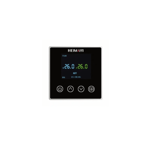
The implementation of building automation systems which include proper installation of room temperature controllers results in measurable energy savings. The data provides following evidence of what energy-saving results.
Documented Energy Reduction
Buildings which install complete building automation systems achieve 15 to 30 percent energy reduction during their initial operational year. The U. S. Department of Energy notes that smart building systems can reduce energy consumption by up to 30 percent compared to non-automated buildings.
HVAC optimization drives the majority of these savings. According to Thunder Said Energy, analysis of 45 real-world case studies shows:
The average air conditioning savings reach 32 percent which extends between 20 and 45 percent. The average heating system savings reach 30 percent which extends between 14 and 25 percent. The overall average savings across all building systems reach 34 percent.
Where the Savings Come From
Zone-Level Optimization: The practice of conditioning occupied spaces only eliminates energy waste which occurs when spaces remain unoccupied. The dental office operates six rooms which remain active throughout the day but two rooms serve as common usage areas. Energy use for occupancy-based control matches the actual demand for energy.
Setback Scheduling: The system applies automatic temperature adjustments which maintain unoccupied areas at lower heating and cooling levels. The energy savings from a 1°C temperature setback range between 5 and 10 percent.
Demand-Controlled Ventilation: The system uses CO₂ sensors to control outdoor air intake according to real-time occupancy data instead of using predefined schedules. The system operates as an energy-saving mechanism which stops excessive ventilation during times of low occupancy.
BAS algorithms determine the essential runtime requirements for comfort achievement according to occupancy patterns while they create a path to eliminate unnecessary pre-conditioning operations.
Payback Periods
Payback Periods
Energy savings translate to financial returns. BAS projects completed between 2020–2025 report average payback periods of 2 years, down from 5–10 years in earlier decades. The improvement comes from:
- Lower hardware costs for controllers and sensors
- Standardized protocols which reduce integration difficulties
- Enhanced software tools which support system setup and deployment
- Wireless solutions which remove the need for expensive electrical wiring installation.
A commercial building covering 50,000 square meters which spends 500,000 on HVAC energy costs will receive a cost increase of 20500,000 per year. A BAS investment of 200,000 will generate returns after 24 months which will produce annual savings of 100,000 throughout the system’s 15 to 20 year operational period.
Common Integration Challenges and Solutions
Even well-planned integrations encounter issues. The following section presents the most frequent issues together with their corresponding solutions.
Challenge 1: Protocol Mismatches
The Problem: Your room controllers speak Modbus RTU, but your BMS only has a BACnet/IP driver. Or you have legacy LonWorks devices that need to integrate with a modern BACnet system.
The Solution: Protocol gateways translate between different protocols. A Modbus-to-BACnet gateway reads Modbus registers and presents them as BACnet objects. These devices cost $200–500 and eliminate the need to replace functional hardware.
For wireless protocols, MQTT has emerged as a common translation layer. The devices send their data to an MQTT broker which the BMS uses to receive specific data streams. This process allows the BMS system to operate independently from the device protocols used.
Challenge 2: Wiring Distance Limitations
The Problem: RS485 networks have distance limitations — typically 1,200 meters at lower baud rates. The distance limits become incompatible with operations of large buildings and campus environments.
The Solution: Install RS485 repeaters to extend network reach. The use of fiber optic converters enables complete elimination of distance limitations while delivering electrical isolation. The use of BACnet/IP routers enables network segmentation into multiple segments which operate with individual MS/TP networks.
Wireless protocols such as LoRaWAN provide complete freedom from wiring distance limitations in extremely large installations. A single gateway covers kilometers.
Challenge 3: Intermittent Communication
The Problem: Controllers randomly drop offline. The system experiences intermittent data updates. The alarms produce false network outages through their failure detection system.
The Solution: Physical layer testing requires assessment of three key areas.
Shielding: Verify continuous shield grounding at one point only Termination: Confirm 120Ω termination resistors at both network ends Biasing: Ensure proper biasing resistors for reliable idle-state voltage
Topology: Eliminate “star” topologies; stick to proper daisy-chain wiring
Baud Rate: Reduce baud rate if experiencing errors; slower is more reliable For wireless systems check signal strength and interference. Use gateways or repeaters to extend coverage area.
Challenge 4: Legacy System Integration
The Problem:You’re upgrading a building with pneumatic controls or early electronic systems Complete replacement is too expensive but you need modern integration.
The Solution: pneumatic-to-DDC converters install electronic controllers that operate existing pneumatic valve actuators to replace pneumatic thermostats Wireless retrofit controllers install in existing thermostat locations without the need for new wiring Protocol gateways enable connection between outdated networks and new BAS systems.
Black Ant’s T6 wireless room temperature controller with LoRa or 4G communication enables exactly this scenario The installation process allows controllers to operate without wired connections to a central control panel The wireless network handles communication and the controllers integrate with existing valves and HVAC equipment Learn more about wireless retrofit options →
Conclusion: From Components to Outcomes
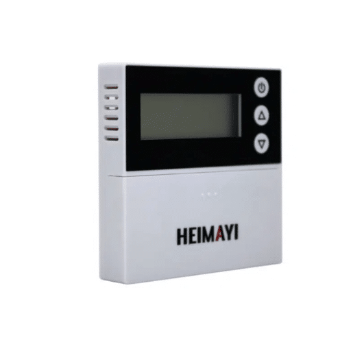
Building automation systems transform buildings from their original static state into environments which demonstrate active and successful operational capabilities. The system needs effective field-level integration work because it depends on that particular aspect for its overall performance. Room temperature controllers serve as the main point where building automation technology delivers its advantages to both occupants and energy management systems.
The core concepts of the system function as basic elements. The system requires sensors for measurement purposes. Controllers make decisions based on input from sensors. Actuators perform their functions according to the operators. Protocols enable communication between network devices. The system achieves energy savings between 15 and 30 percent through its four architectural tiers which operate together with their components.
The implementation requires attention to specific details. The installation of BACnet MS/TP wiring needs to adhere to RS485 best practices. The Modbus register maps need to receive complete and accurate documentation. The existing system requires assessment to confirm that wireless coverage exists everywhere. The control system requires special configuration to achieve both precise measurement and stable performance.
The same fundamental rules apply whether you need to connect multiple controllers in a small office environment or operate thousands of controllers throughout an entire campus. The first step requires organizations to develop a precise installation plan. After that installation process organizations need to implement their system through structured installation and commissioning processes. The testing process needs to include every component of the system. The testing process requires the creation of complete documentation.
The end result produces energy savings which benefit the building while creating better conditions for building occupants and providing modern facility management systems with operational insights. Your room temperature controllers are the critical bridge between building-wide strategy and zone-level execution. You need to create a proper connection through the construction of that bridge.







