

Level Measurement in Sealed Tanks: DP Transmitter Calibration
Accurate level measurement in sealed tanks is critical across various industries which need this measurement to achieve operational efficiency while maintaining safe conditions during their production of high-quality products. A Differential Pressure (DP) transmitter is one of the most commonly used tools for this purpose but operators need to perform proper device calibration in order to achieve accurate measurements during these challenging testing environments. This blog post presents the essential elements of DP transmitter calibration which seals tanks because it shows the times to implement this method and the complete procedures needed for calibration. The guide provides complete knowledge which enables both skilled engineers and beginners to use tank level measurement systems without any difficulty.
Introduction to Level Measurement in Sealed Tanks

The process of level measurement in sealed tanks requires the total material measurement which exists inside a completely closed tank. The process serves two purposes because it helps to achieve proper inventory control and protects operational safety while maximizing production efficiency. The most reliable method for sealed tanks is differential pressure (DP) measurement which calculates the liquid level based on the pressure difference between the top and bottom of the tank. The use of calibrated DP transmitters allows operators to measure all tank pressure and liquid density variations which results in accurate and stable measurements that remain reliable under difficult operational conditions.
Importance of Accurate Level Measurement
Organizations need accurate level measurement systems to maintain industrial safety. These systems provide operational efficiency benefits and help reduce operational expenses. The following five points demonstrate why accurate level measurement is essential for industrial operations:
1
Process Safety
The correct tank level measurement prevents both overfilling and dry tank operation which results in equipment damage and hazardous situations. The proper control of liquid levels in chemical storage tanks prevents dangerous leaks and explosions from occurring.
2
Optimized Production Efficiency
The accurate level monitoring system allows manufacturers to reach their highest production capacity while minimizing their consumption of raw materials. The precise management of liquid levels enables manufacturers to achieve their production targets through waste elimination and production downtime.
3
Inventory Management
Businesses use reliable level measurement systems to produce precise inventory records which enable better supply chain management. Oil and gas operations depend on real-time inventory tracking because it directly influences their operational efficiency and financial performance.
4
Cost Control
The overfilling of tanks results in resource wastage when tank capacity remains unutilized. The operators can control their operational costs and material waste through accurate material level measurement.
5
Regulatory Compliance
All industries must comply with enforcement regulations which specify proper material storage and handling procedures. Level measurement systems enable businesses to meet environmental and safety standards which protects their reputation and prevents legal problems.
Role of DP Transmitters in Tank Level Measurement
Differential Pressure (DP) transmitters serve as vital tools which provide accurate measurement of tank liquid levels through their operation. The devices function by measuring pressure differentials which they use to determine the liquid volume present in tanks. The system operates correctly because all its parts work together to produce exact readings which enhance both operational performance and security. The tank level measurement system needs DP transmitters to execute five crucial tasks that include these specific functions.
- ✦
Accurate Level Measurement
The system provides precise liquid level measurements because it uses pressure changes to determine fluid height measurements which work effectively in challenging operating conditions. - ✦
Compatibility with Various Fluids
The devices show versatility by tracking different types of liquid levels which include hazardous materials and petroleum products and water and various other liquids to meet multiple industrial requirements. - ✦
Real-Time Monitoring
Operators can use DP transmitters to monitor tank levels which enables them to take immediate actions when they observe current tank conditions to avert both overfilling and underfilling situations. - ✦
Temperature and Pressure Compensation
The advanced DP transmitters use special methods to measure temperature and pressure changes which maintain measurement reliability through their compensation techniques. - ✦
Cost-Effective and Scalable Solutions
The economical design of DP transmitters allows their simple installation into current systems which makes them an affordable solution for both small and large tank level control operations.
Applications in Various Industries
All industrial sectors depend on differential pressure (DP) transmitters as vital instruments for monitoring and managing tank liquid levels with high accuracy and reliable results. The five main industries which use DP transmitters as essential equipment demonstrate their critical importance.
| Industry | Primary Application | Key Benefit |
|---|---|---|
| Oil & Gas | Storage tank levels of crude oil, refined products, and liquid materials | Accurate tank level measurements for process safety and regulatory compliance |
| Chemical | Liquid chemicals in production tanks in dangerous or corrosive settings | Proper tank conditions supporting process control and product quality |
| Water & Wastewater | Water distribution management and wastewater processing control | Proper operation for filtration and treatment processes |
| Food & Beverage | Liquid levels in storage tanks for milk, juice, and brewing solutions | Hygienic production standards with boosted efficiency |
| Pharmaceutical | Tracking highly purified liquids for pharmaceutical products | Product quality while meeting strict regulatory requirements |
The three main benefits of DP transmitters which deliver precise results and multiple applications at affordable prices make these devices essential for businesses that need to manage their tank levels.
Core Concepts of DP Level Measurement
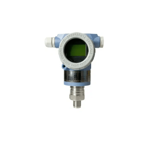
Differential Pressure (DP) level measurement functions as a standard technique which enables tank and vessel operators to determine their fluid levels. The system operates through its differential pressure mechanism which measures the pressure differences existing between two designated points inside the tank system. The system determines fluid levels through pressure differentials which operate with a complete range of tank contents including liquids and gases and slurries.
Basic Principle
The DP transmitter system measures pressure differences between its high pressure HP side which connects to the tank bottom and its low pressure LP side which either vents to the atmosphere or connects to a reference pressure. The measurement of differential pressure enables the calculation of fluid column height because it combines both fluid density and gravitational force.
Core Formula
ΔP = ρ × g × h
ΔP
Differential Pressure
Differential Pressure
ρ
Fluid Density
Fluid Density
g
Gravitational Acceleration
Gravitational Acceleration
h
Fluid Height (Level)
Fluid Height (Level)
Various Application Types
Open Tanks
The system operates its LP side at atmospheric pressure which creates standard operating conditions used in water treatment plants and water storage facilities.
Closed Tanks
The system needs to create a link that connects the tank’s low-pressure section with its upper tank space which uses vapor pressure to manage tank pressure levels.
Accuracy and Versatility
Modern DP transmitters provide high accuracy performance that reaches ±0.1% of the span which makes these devices suitable for essential operations in oil and gas and pharmaceutical and food and beverage sectors. The system can handle low-density liquids and high-viscosity materials which include fluids that experience temperature changes through its advanced temperature and density compensation algorithms.
| Advantages | Challenges |
|---|---|
| Cost-Effective: The cost of DP transmitters remains lower when compared to advanced level measurement systems which use radar or ultrasonic technology. | The measurement process requires complete understanding of fluid density because accurate results depend on this information. |
| Reliability in Harsh Environments: The system operates successfully during situations that involve extreme temperature and pressure conditions. | The temperature and composition changes require appropriate correction methods because they will create measurement errors. |
| The system functions correctly for both small operational setups and extensive industrial operations. | The process of impulse line maintenance holds vital importance because any blockages or leaks will affect measurement results. |
The combination of precise design techniques with cutting-edge sensor systems and digital technology integration provides a dependable solution for DP level measurement across various industrial applications. The future of DP technology will develop through its integration with artificial intelligence and machine learning algorithms which will improve predictive maintenance and operational efficiency.
Understanding Differential Pressure
Industrial processes depend on Differential Pressure (DP) as a core measurement tool which allows them to measure pressure differences between two points within their operational systems. The measurement system enables operators to monitor and manage flow rates and liquid heights and pressure measurements across multiple operational tasks which include running filtration systems and fluid transfer operations and tank volume assessment. The companies reach operational efficiency through exact process readings while they ensure workplace safety and compliance with all required regulations.
The measurement of differential pressure requires specific sensor devices which transform pressure variations into signals that can be analyzed through digital systems. The accuracy of DP measurement systems has improved through technological innovations that introduced piezoresistive sensors and capacitive sensors as new technologies. Piezoresistive sensors function as exceptional pressure detection tools because they identify extremely small pressure variations with their highly sensitive detection capabilities which make them suitable for use in oil and gas and chemical industry-related work.
The current research demonstrates that the environmental monitoring field increasingly uses DP measurement to assess water flow rates in water management systems. The 2023 report projects that the worldwide pressure sensor market will experience a 7.9% compound annual growth rate which will bring the market value to $24.7 billion by 2028. The demand for products has increased because devices which use IoT technology now permit users to monitor their devices in real time while making future predictions.
The evaluation of filter performance stands as another important use case. The differential pressure across the filter increases when the filter blocks flow because the filter becomes blocked. The process of monitoring these shifts helps to protect equipment from damage while also reducing the risks of unexpected service interruptions. The proper maintenance of DP systems in HVAC operations plays a vital role in achieving better energy efficiency and improved indoor air quality.
The future development of DP technology will proceed through its incorporation into Industry 4.0 solutions which will use AI and machine learning to boost their pattern recognition and anomaly detection capabilities. The program will help companies to improve their operational efficiency while spending less money on maintenance and strengthening their security protocols.
High-Side and Low-Side Pressures Explained
HVAC and refrigeration systems achieve their operational efficiency through high-side and low-side pressures, which function as vital operational parameters that control their performance. The refrigeration cycle consists of two pressure zones, which include a high-pressure side that carries discharge and a low-pressure side that handles suction.
High-Side Pressure
Location: Measured at the condenser — the section that handles heat dissipation.
Typical Range: 200 PSI to 300 PSI (varies by refrigerant and outside temperature).
Risk: High pressure values beyond the limit result in component damage and operational inefficiency.
Low-Side Pressure
Location: Measured at the evaporator — where refrigerant absorbs heat from the environment.
Typical Range: 20 PSI to 70 PSI (varies by system design and refrigerant type).
Risk: Excessively low pressure reduces cooling capacity and creates risk of ice formation in the evaporator.
Smart sensor technology allows for constant pressure monitoring that delivers precise data which helps identify system malfunctions and find leaks. The integration of pressure sensors with AI-based diagnostic systems enables operators to forecast pressure changes, which allows them to optimize system control for maximum energy efficiency. Modern systems that use these new technologies achieve 25% energy savings, which also improves their overall system reliability according to industry reports.
HVAC systems and refrigeration systems need operators to maintain high-side pressure and low-side pressure balance, which enables the systems to operate at maximum efficiency. The achievement of desired results requires three main strategies, which include routine system evaluations and maintaining appropriate refrigerant amounts and using sophisticated monitoring systems.
Sealed Tank Dynamics
Sealed tank dynamics study fluid and gas movement in closed systems that contain pressure and temperature and volume which follows thermodynamic rules. The essential functions of sealed tanks enable industrial operations and HVAC system functions to proceed without interruption. The three primary factors which influence tank dynamics are fluid or gas type and tank material and operating conditions of the system.
The research outcomes enable scientists to comprehend the effects of pressure and temperature changes on sealed systems by studying recent technological developments. The research shows that a sealed vessel will experience a 10 to 15 percent increase in internal pressure when the temperature rises by 10 degrees Fahrenheit because of the fluid’s compressibility characteristics. The selection of materials for a project contains important value because tanks constructed from high-strength alloys which include stainless steel 316 produce better protection against high-pressure situations that can cause structural failure.
The current monitoring systems use IoT-enabled sensors to deliver real-time information about pressure and temperature fluctuations that occur in sealed tanks. The systems provide predictive maintenance capabilities which result in a 30% reduction of downtime according to industrial-scale deployment reports. The use of computational fluid dynamics (CFD) simulations serves as an essential tool which enables tank design optimization because it predicts fluid behavior during specific operational conditions.
The sealed tanks maintain their structural strength and safe operation through strict compliance with ASME Boiler and Pressure Vessel Code (BPVC) standards. The proper pressure relief valve calibration together with required inspection schedule compliance helps reduce overpressurization risks which support system efficiency and operational lifespan.
Step-by-Step Calibration Procedure for DP Transmitters

Industrial applications depend on Differential Pressure (DP) transmitters as essential elements because they deliver precise pressure data which enables effective control of industrial systems. The calibration process needs to be performed correctly because it serves as the foundation for maintaining accurate and dependable performance. The following document presents a complete calibration process for a DP transmitter which follows established standards and current operational techniques:
1
Gather Required Tools and Equipment
The following tools and devices need to be present for the project work to proceed:
- A high-precision pressure calibrator or deadweight tester.
- HART communicator (if the DP transmitter is HART-enabled).
- The system needs a power supply which operates at 24V direct current.
- Test manifold and proper tubing for connections.
- The multimeter assists in current measurement throughout the 4-20 mA loop system.
2
Verify Safety Precautions
- The team needs to depressurize the system before they can proceed to cut off power to the DP transmitter which connects to the process line.
- The team needs to check whether the valves are open for equalization and closed for high and low-pressure block valves.
- The team needs to follow all site-specific lockout and tagout procedures to maintain safety during the calibration process.
3
Inspect the Transmitter
- The team needs to perform a visual examination of the DP transmitter to search for signs of damage or leaks or corrosion.
- The team needs to check electrical connections to ensure proper insulation and secure fittings.
4
Set Up the Calibration Equipment
- The team should connect DP transmitter high-pressure and low-pressure ports to the pressure calibrator through the manifold and tubing system.
- The team should supply power to the transmitter before they start direct current measurement through multimeter installation in series.
- The user must connect a HART communicator to establish communication with the HART-enabled transmitter.
5
Zero Calibration
- The equalizing valve needs to be opened so that the transmitter’s diaphragm pressure will reach equalization.
- The transmitter output signal needs to be checked because standard configuration should produce 4 mA output.
- The output will reach 4 mA which needs to be corrected through the zero-adjustment screw or software interface (HART communicator) when there is an output deviation.
6
Perform Span Calibration
- The technician needs to close the equalizing valve before using the calibrator to create a known pressure which matches the upper range (full scale) of the transmitter.
- The system should present an output signal that equals 20 mA.
- The output needs to match the applied pressure so the technician should use the span-adjustment controls or HART communicator for adjustment.
- The transmitter requires pressure testing which should be conducted at three different increments 25% 50% and 75% of its total calibrated range.
- The output needs to be recorded during every step because the transmitter should produce a linear response. Any discrepancies indicate potential non-linearity that may require further inspection or factory recalibration.
7
Document Calibration Results
- The technician needs to record all information which includes applied pressures and observed outputs and any adjustments which were performed.
- The report needs to include serial numbers and calibration timestamps and environmental conditions so that traceability can be maintained.
8
Reinstall and Recommission
- The technician needs to disconnect the calibration equipment before reattaching the transmitter to the process line.
- The technician should increase system pressure gradually while testing whether the transmitter functions properly during standard operational conditions.
💡
Notes on Modern Calibration Techniques
The new digital communication standards HART and FOUNDATION Fieldbus which emerged through recent technological advancements now permit more detailed diagnostic testing and remote calibration capabilities. The development of automated calibration systems now enables users to achieve higher precision results while minimizing the chance of human mistakes. The International Society of Automation (ISA) standards for pressure calibration should be followed to maintain device reliability and ensure accurate data results throughout its operational life.
Overview of Calibration Process
The calibration procedure needs a systematic approach which produces accurate results for testing pressure measurement devices. The procedure includes three main stages which need to be followed:
- Prepare the equipment by checking its cleanliness and working conditions and its ability to meet required standards before starting the calibration process. The calibration process requires specific environmental conditions because temperature and humidity both impact the calibration process. According to NIST guidelines pressure devices experience major errors when ambient temperature exceeds the range of ±1°C.
- Selection of Calibration Equipment: Selecting high-quality reference standards and calibrators is vital for ensuring precise measurements. Digital pressure calibrators achieve typical measurement uncertainty which reaches ±0.01% of the measured value because they use advanced microprocessor technology. The reference device should always have a higher accuracy than the instrument being tested—generally at least four times better, as recommended by the Test Accuracy Ratio (TAR) standards.
- Application of Known Input Values: The device under test (DUT) operates under controlled conditions while receiving predefined pressure inputs to measure its performance. A comparison is made between the DUT’s output and the reference standard to identify any deviations. Modern calibrators perform this task through automated processes which use digital displays to show real-time discrepancies that can be detected at sub-pascal levels.
- Adjustment and Fine-Tuning: The DUT needs corrective measures because it shows more than one acceptable error range which should be fixed through internal mechanism and software algorithm adjustments. The procedure restores instrument accuracy to its required operational standards which include output accuracy of ±0.1% for full-scale output.
The testing process needs to evaluate the instrument’s accuracy which requires testing at all examination checkpoints after the recalibration process. The calibration process needs all maintained records to document which equipment has been found in its original state and returned to its original state together with the collected environmental data and equipment inventory. The ISO/IEC 17025 standards establish requirements for organizations to follow which include traceability requirements because they define the standards needed to produce test results that can be audited.
The advanced monitoring systems which include condition-based calibration scheduling show increased usage for monitoring systems which aim to determine optimal recalibration periods. Research shows that organizations can achieve 25 percent savings in calibration expenses through the five-year audit process by implementing predictive maintenance which uses calibration-based IoT solutions.
The calibration process achieves better performance through the implementation of new technologies which include AI-based diagnostic tools and wireless communication systems. Organizations achieve better measurement accuracy and reduced operational interruptions by using data-driven approaches which follow international standards for measuring pressure in vital systems.
Zero and Span Adjustments
The pressure measurement instrument calibration process needs both zero and span adjustments because those adjustments help establish measurement precision while preserving instrument operational capability. The zero adjustment enables an instrument to display “zero” when there is no pressure present by correcting its initial measurement point. The span adjustment allows the instrument to reach its highest pressure reading capacity at a specific location within its measurement range. The calibration process needs both adjustments because they help maintain precise measurements while technicians need them for their calibration work.
Recent advancements in calibration technology have made zero and span adjustment procedures easier to perform. The calibration system now uses AI algorithms to examine past calibration records and determine the best adjustment settings for automated systems. Modern IoT-enabled pressure transducers can perform self-calibration functions because they adjust their zero and span settings based on current environmental factors and system performance. The automation system enables a 40 percent reduction in manual work which leads to better operational productivity according to industry reports.
Research from recent case studies indicates that poorly calibrated instruments can contribute to measurement errors exceeding 2% which can lead to costly deviations in industrial processes. ISO/IEC 17025 standards require all equipment which operates in high temperature environments and high vibration environments to undergo regular recalibration testing. Integrated digital monitoring systems that track drift in zero and span values enhance precision, enabling organizations to mitigate potential errors before they impact operations.
The combination of these technologies with regular system maintenance and best practice implementation creates a foundation that supports accurate pressure measurement through zero and span adjustments.
Wet vs. Dry Legs Impact on Calibration
The process of selecting between wet leg and dry leg system configurations determines the precision of differential pressure transmitter calibration measurements. Process systems achieve precise measurement results by understanding various measurement techniques which affect their accuracy and operational efficiency. The following five essential elements demonstrate how wet legs and dry legs affect calibration results:
| Factor | Wet Legs | Dry Legs |
|---|---|---|
| Density | Depend on fixed density of fill fluid which changes with different temperature conditions. | Use air as filling material — less sensitive to density changes but face condensation problems in moist conditions. |
| Condensation | Maintain their liquid-filled system — requires selecting fill fluids that meet operating temperature requirements. | Can experience condensation in high humidity or cold conditions, causing pressure measurement problems and calibration errors. |
| Fluid Maintenance | Require maintenance to ensure fill fluid stays clean and at correct operational level; fluid loss causes calibration drift. | Less fluid maintenance work but requires inspecting for condensation and blockage issues. |
| Temperature | Use thermal expansion/contraction as a direct measurement method; requires temperature-controlled environments or compensated fluids. | Maintain shape better under temperature changes, yet pressure changes occur because of air temperature variations. |
| Response Time | Slower response times because liquid fill needs viscosity and inertia to complete movement, causing calibration system delays. | Faster response times, but handling transient pressure spikes creates challenges for calibration procedures. |
Operators can achieve optimal system performance through their analysis of these essential factors which enables them to choose suitable leg configurations and establish customized calibration methods.
Calculations and Formulas for Level Measurement

Industrial level measurement requires exact mathematical results which need special mathematical formulas that must be developed for each specific operational environment. The calculations use hydrostatic pressure principles together with fluid density data and storage vessel geometric dimensions.
Hydrostatic Pressure Formula
The basic equation which calculates hydrostatic pressure-based level measurement uses the following relationship:
P = ρ × g × hThe formula calculates hydrostatic pressure to determine fluid height in open tank systems because tank pressure increases with the height of fluid above the tank base.
Differential Pressure for Closed Tanks
The differential pressure measurement technique uses differential pressure (DP) as the standard method to determine levels inside either pressurized systems or closed systems:
DP = (ρ × g × h) + PₐWhere Pₐ = Additional pressure in the tank headspace (Pa). Calibration factors must maintain their proper functioning ability because they need to control all vapor and gas pressures that exist in the tank headspace.
Volume Calculation for Cylindrical Tanks
To determine liquid volume more accurately the tank requires both its horizontal and vertical cylindrical measurements. For horizontal cylindrical tanks:
Volume = π × r² × L × (h/D)- r = The tank’s radius measurement in meters
- L = The tank’s length measurement in meters
- h = The height measurement of fluid in meters
- D = The tank’s diameter measurement in meters
Temperature Compensation
The temperature changes to fluid density which leads to incorrect level measurements. The temperature correction factor (β) serves to correct density calculations:
ρ_adjusted = ρ_reference × [1 - β × (T_actual - T_reference)]- T_actual = Actual fluid temperature (°C)
- T_reference = Reference temperature (°C)
- β = Thermal expansion coefficient, specific to the fluid
Utilizing Real-Time Data Integration
Modern systems combine real-time sensors with digital controllers to achieve better performance accuracy. Radar and ultrasonic level sensors measure fluid surface distance through:
Level = (c × t) / 2- c = Speed of sound/electromagnetic wave (m/s)
- t = Signal travel time (s)
📊 Example Data Validation
A cylindrical tank which has a diameter of 2 meters contains liquid with a density of 1000 kg/m³. The hydrostatic pressure measurement shows a value of 29,430 Pa. The height is derived through the formula P = ρ × g × h:
h = P / (ρ × g) = 29,430 / (1000 × 9.81) ≈ 3 mDetermining Upper and Lower Range Values (URV & LRV)
The Upper Range Value (URV) and Lower Range Value (LRV) function as essential calibration standards which enable the proper operation of level measurement systems. The instrument uses these values to define its operational boundaries which it must maintain throughout its specified measuring range.
To determine the URV and LRV for a cylindrical tank, the following details are required:
Tank Dimensions
Diameter = 2 m
Height = 4 m (assumed)
Fluid Properties
Density = 1000 kg/m³
(water at ambient conditions)
Formula
P = ρ × g × h
| Parameter | Condition | Value | Signal |
|---|---|---|---|
| LRV (Lower Range Value) | Empty tank (h = 0 m) | 0 Pa |
4 mA |
| URV (Upper Range Value) | Full tank (h = 4 m) | 39,240 Pa |
20 mA |
The tank needs temperature compensation for density changes because its operation depends on changing environmental conditions. The instruments need to measure environmental elements which include installation on uneven surfaces because these factors affect their measurement accuracy. Operators establish measurement system reliability through precise URV and LRV definitions which they calibrate according to ISO 5167 and API 650 industry standards. The measures decrease system inefficiencies while they enhance safety and control of operational processes.
Mathematical Formulas for DP Level Measurement
The fundamental concept behind Differential Pressure (DP) level measurement operates based on the link between liquid column height and the pressure it generates. The main equation that controls DP level measurement can be represented by the following relationship:
Primary Equation
P = ρ × g × h
P
Pressure (Pa or psi)
ρ
Density (kg/m³ or lb/ft³)
g
9.81 m/s² or 32.174 ft/s²
h
Height of liquid column (m or ft)
Application in Open Tank Measurement
The DP transmitter for open tanks measures the hydrostatic pressure that the liquid column exerts on the system. The equation above allows us to determine the liquid level by rearranging the formula to solve for height (h):
h = P / (ρ × g)The calculated height reflects the liquid level in the tank since the pressure reading corresponds directly to the height of the liquid column.
Application in Closed Tank Measurement
The design of pressurized or closed tanks requires special procedures which must account for the existing gas pressures within the system. The total measured DP can be expressed as:
DP = (ρ × g × h) - PtWhere Pt is the pressure from the gas phase or blanket pressure (Pa or psi).
h = (DP + Pt) / (ρ × g)Measurement Accuracy Requirements
- Density Compensation: The measurement of temperature is essential because temperature changes impact liquid density which demands temperature-adjusted density measurements for correct results.
- Calibration: The calibration process needs to be performed frequently together with proper isolation procedures during transmitter commissioning to control errors which occur through drift and external influences.
- Installation Conditions: Transmitter installation needs to follow precise leveling requirements while maintaining established reference points to stop inclinations from creating measurement errors.
- Temperature or Multiphase Factors: The measurement of multiphase liquids at different temperatures needs extra corrections to maintain accuracy.
Real-World Example Calculation
A tank contains water (ρ = 1000 kg/m³, 20°C). The transmitter measures a differential pressure of 50 kPa, with a blanket pressure of 20 kPa applied in the gas phase (g = 9.81 m/s²).
h = (DP + Pt) / (ρ × g)
h = (50,000 + 20,000) / (1000 × 9.81)
h ≈ 7.14 meters
The current liquid level in the tank measures approximately 7.14 meters according to this calculation.
Example Calculations in Real-World Scenarios
The industrial scenarios below demonstrate how pressure-based liquid level calculations work while showing the formula’s practical value and accurate results.
| Industry | DP (Pa) | Pt (Pa) | ρ (kg/m³) | Result (h) |
|---|---|---|---|---|
| Chemical (Sulfuric Acid) | 85,000 | 15,000 | 1,800 | ≈ 5.64 m |
| Water Treatment | 40,000 | 10,000 | 1,000 | ≈ 5.10 m |
| Oil Refinery (Crude Oil) | 60,000 | 25,000 | 850 | ≈ 9.99 m |
| Beverage (Beer) | 30,000 | 5,000 | 1,050 | ≈ 3.34 m |
| Pharmaceutical | 75,000 | 22,000 | 1,200 | ≈ 8.29 m |
Common Challenges in DP Transmitter Calibration

The process for calibrating differential pressure transmitters which industrial systems use needs expert knowledge to execute but faces multiple obstacles during its implementation. The five common challenges which occur in this process get explained through their complete operational impacts which need to use both data and explanations as evidence.
Challenge 1
Temperature Variations
DP transmitters experience measurement drift issues because process temperature changes disrupt their operation. The temperature variations lead to changes in process fluid density and transmitter components which cause measurement errors.
Data: For every 10°C increase beyond the calibrated range, an error of approximately 0.1% of full-scale output is observed. The solution requires proper insulation together with compensation methods.
Challenge 2
Improper Zeroing & Span
The transmitter calibration process needs accurate zero and span settings because incorrect span setup creates measurement errors. The problem occurs when operators forget to perform all required system adjustments.
Data: A deviation of ±0.2% of the LRV has been reported in improperly zeroed transmitters, significantly affecting accuracy in low-differential pressure applications.
Challenge 3
Process Leaks / Blockages
The pressure transmission process suffers from disruptions caused by process fluid leaks or impulse tubing blockages which result in both incorrect readings and unstable signals. Blockages create when harmful materials form deposits.
Data: Studies have shown that up to 15% of field devices experience performance issues because blockages remain hidden from detection.
Challenge 4
Static Pressure / Overrange
Internal sensing elements which detect high static pressure and exceed transmitter design limits through over-ranging conditions must satisfy their operational requirements. The calibration errors remain in effect until pressure conditions return to normal.
Data: Over-ranging incidents result in 1% total accuracy loss while decreasing transmitter operational life by 20%.
Challenge 5
Environmental Interference
Transmitter performance and signal integrity suffer from vibrations and electromagnetic interference (EMI) and extreme environmental conditions which include high humidity and corrosive atmospheres.
Data: EMI causes signal deviations that reach ±0.5% of the full-scale output in facilities which lack sufficient shielding.
The solution to these challenges depends on executing strict calibration procedures and following maintenance times and equipment specifications, which help ensure that DP transmitters produce dependable and accurate results for industrial use.
Troubleshooting Temperature Fluctuations
The differential pressure (DP) transmitters experience temperature changes because of multiple environmental conditions. The process of finding and fixing these problems must be conducted because it leads to better operational precision and system trustworthiness. The following list contains five temperature-related factors that create problems which require specific solutions to be solved.
| Cause | Solution |
|---|---|
| Thermal Expansion in Sensor Materials | Use temperature-compensated sensors. The differential pressures experience changes because the sensor components expand and contract when temperatures change. Regular temperature compensation checks through calibration processes are required. |
| Ambient Temperature Changes | Install transmitter system inside temperature-controlled enclosures or with proper insulation in extremely cold and hot weather conditions. |
| Oil Fill Fluid Viscosity Changes | Use fill fluids that maintain low viscosity sensitivity across all operating temperatures. The sensor’s pressure measurement system experiences changes because temperature changes create viscosity alterations in oil fill fluids. |
| Electrical Component Drift | The transmitter should undergo diagnostic tests at regular intervals while selecting electronic models which include temperature compensation systems as their base requirement. |
| Process Temperature Gradients | The entire process piping system requires uniform thermal insulation while temperature sensors need installation to detect and control temperature gradients created by uneven process temperatures and localized hotspots. |
Addressing Seal Fluid Density Changes
Seal fluid density undergoes changes because of varying temperature and pressure conditions which result in incorrect measurements for differential pressure (DP) transmitters. The main elements which affect seal fluid density variations through different temperature changes and environmental factors and the specific characteristics of seal fluids determine the density variations. The start of measurement errors which create operational inefficiencies and safety risks begins with the occurrence of density fluctuations.
Reasons Which Cause Seal Fluid Density Changes
Thermal Expansion
Seal fluids experience temperature changes which cause their volume to expand or contract resulting in density changes. Silicone oil which serves as a standard seal fluid demonstrates a thermal expansion coefficient of approximately 0.00096/°C.
External Pressure Effects
Seal fluids experience compression when atmospheric or process-side pressure changes occur. Certain seal fluids exhibit density changes that reach 0.5% at extreme pressures which exceed 1000 psi.
Contamination or Degradation
Seal fluid undergoes degradation after it experiences prolonged contact with process contaminants or high-temperature environments. The fluid alterations lead to density changes which result in decreased measurement accuracy.
Mitigation Strategies
- Temperature Compensation
Modern DP transmitters equipped with built-in temperature sensors maintain their measurement accuracy by adjusting their readings to match actual density changes that occur with temperature variations. The use of temperature compensation algorithms results in improved measurement accuracy for the system.
- Using Low-Thermal-Expansion Fluids
The application of seal fluids that contain low thermal expansion coefficients from fluorocarbon-based fluids leads to decreased density variations across different temperature ranges. Fluorocarbon fluids demonstrate minimal expansion rates which reach 0.0001/°C thus maintaining their physical properties.
- Routine Seal System Maintenance
The process of inspecting seals and replacing degraded seal fluids enables operators to achieve their desired density performance. The process of analyzing fluid samples enables the identification of contamination issues which requires immediate corrective measures.
- Pressure-Resistant Designs
The system maintains fluid density stability through diaphragm seals and high-pressure capillaries which operate under pressure changes. These designs prove essential for operations that take place in extreme conditions which occur during deep water missions and vacuum treatment processes.
📈 Supporting Data
Field Study Results
The 2022 case study showed that DP transmitters with temperature-compensated seal systems achieved 15% better accuracy under fluctuating temperatures when compared to standard systems.
Seal Fluid Performance
High-performance silicone oils maintain density changes within ±0.2% during a 100°C temperature increase, while regular oils can exhibit density changes exceeding ±1.5%.
The implementation of proper seal fluid density control methods combined with advanced technological solutions will result in substantial accuracy improvements for differential pressure measurements. This solution brings about enhanced system reliability while improving process control capabilities needed for critical industrial operations.







