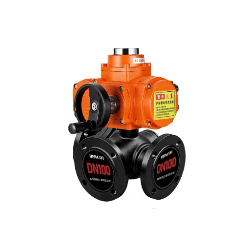
Control Valve Sizing: Guide to Valve Selection & Size
Control valves are essential for regulating the flow, pressure, and temperature of diverse manufacturing processes. However, choosing the most promising and appropriate valve size or type can be challenging and may lead to inefficiencies, performance problems, and other concerns in a system. For instance, control valve sizing and selection are concepts that should be well understood by Engineers, Technicians, and Decision Makers, among other individuals concerned with operations improvement. The current work engages other experts and authors to gain a deeper understanding of valve sizing and the proper identification of the most appropriate application. The paragraphs below describe valve selection in some detail, outline simple steps to follow, and present criteria for considering a valve for a given system.
Understanding Control Valves

Control valves are devices that control fluid flow in systems, regulating flow, pressure, or temperature. They can be enhanced to work by opening or closing a plug or disc-moving device within a valve attached to it, which is controlled by a command. In short, a control valve acts as a moderator, normalizing a system condition to the designed level, thereby improving system performance. It is essential to consider how to size the control valve to meet the system requirements and reduce energy consumption, as well as issues such as leakage and instability.
What is a Control Valve?
In industrial systems, optimizing the flow, pressure, or temperature of fluids is done using control valves, which are mechanical systems that restrict one of the three, depending on the size of the flow passage and conditioned by signals from the controller.
Importance of Valve Selection
The process of assembling and consuming content should always be based on relevancy and factuality and for this reason, promoting the use of appropriate control valves in operation is crucial. Using the wrong control valve types can cause operational failures, energy waste, and even equipment failures. Listed below are five significant factors related to valve selection that must be taken into consideration:
Compatibility with respect to the System
Any type of valve used must be compatible with the fluid running through the system, as well as its operating pressures and temperatures. For corrosive fluids, for instance, valves made of a particular material, such as stainless or alloy steel, are necessary to avoid damage.
Optimization of Energy Consumption
In the right way, how to size a control valve and select it economically for the process, properly sizing the valve to reduce flow losses to a minimum. Unsuitable sizing of a valve can easily result in a lot of energy being lost and hence added operational costs.
Precision in Process Control
Selecting valves that provide tight control of fluid, gas, heat, or power flow ensures process efficiency. Control accuracy can be compromised by excessively restricting control valves or by using large control valves.
Managing Hazards and Risks
Properly selected valves increase the safety of the system by ensuring that the valves can withstand minimum and maximum absolute pressures and withstand failure modes. Improper selection of the valve leads to leakage and malfunction, thereby posing safety risks.
Repair & Maintainability
The use of high-quality materials and a suitable valve design reduces wear and tear, lowering maintenance costs and prolonging the valve’s lifespan. This results in reduced maintenance and overall operating expenses over the long term.
As a result, industries can improve the efficiency of their systems by accounting for these aspects during the valving process.
Types of Control Valves
Control valves are essential in regulating the flow rate, pressure, and temperature in industrial processes. The various types of control valves are discussed below with their major features and applications:
Globe Valves
Globe valves help moderate flow and serve as throttling valves. Further, they operate in linear motion for fluid flow regulation and can be used for on/off or modulation. These types of valves are used primarily in the oil & gas, water, and power industries.
Advantages:
High precision written in numerals in controlling the flow and a high standard of valve sealing.
Applications:
Steam systems, chemical injection, and adjusting flow rates.
Ball Valves
One known trait of ball valves is their low pressure drop while allowing swift action. Such valves apply the principles of rotation and a ball as the closing element.
Benefits:
Effective in situations requiring a closure, inexpensive to maintain, and can last a more extended period.
Uses:
Oil & gas pipelines, heating, ventilation, and air conditioning ducts, and water supply.
Butterfly Valves
They are otherwise known as butterfly valves and are used in areas where space and weight considerations are critical. The primary component of disc-like valves can be rotated within the pipe to allow or restrict the flow of media.
Benefits:
Inexpensive, with a slight pressure drop, and easy to fit in.
Uses:
Distribution of water, sewerage and chemical plants.
Diaphragm Valves
These valves have a material covering the seating surface that can be used to adjust or cut off the flow. They are fantastically used for slurries, corrosive chemicals, or even solid-bearing fluids.
Benefits:
Good sealing, can withstand chemical exposure, and easy to wash.
Uses:
Biological, food and beverage, and water systems.
Plug Valves
These valves have either a cylindrical or a conical plug that rotates to open or close the valve. They are robust and efficient in high-pressure conditions.
Benefits:
Basic design, good closure, and multifunctional.
Uses:
Polymer, chemical, and oil processing, and solids within pipeline
Control Valve Actuators
To a large extent, most modern control valves have actuators. These actuators can be either pneumatic, electric, or hydraulic. Just as with valves, actuators help achieve the goals of automation, effectiveness, and real-time dependability.
The latest in this field is the demand for smart actuators enabled by IoT, which enable remote monitoring and predictive maintenance.
Market Insights and Trends
Looking at market data, the global control valve market is expected to reach $13.8 billion by 2030, with a compound annual growth rate of 6.9%. This can be attributed to the increased use in several industries, including renewable energy, water tech applications, and smart manufacturing. Technological advances in the nature of automation & Energy saving initiatives promote the direction in which control valve technology is headed.
Key Factors in Sizing Control Valves

The importance of proper control valve sizing cannot be overstated, as it ensures high-performing systems, reduced energy consumption, and resilience over extended periods. There are several factors to consider during valve sizing that determine the most appropriate valve for each application. Below is a list of the most critical aspects, followed by recent developments in practice and literature:
1. Check the Flow Rate
This feature makes determining the controlled medium’s flow rate a key factor in selecting control valves. The flow through each control system varies, and this calls for appropriate control valve sizing to handle these controls. Take, for example, industrial settings. In these cases, there may be processes that involve fluid/gas regulation, where the average flow is about 0.10 gallons per minute, while large equipment in another system may control the flow at thousands of gallons per minute.
2. Valve’s Pressure
It is highly significant to understand, along with the pressure drop, ΔP, across the valve, because that is what affects the control more efficiently. A well-designed operating system would set the pressure change across the control valve to an average of 10-20% of the system pressure. The pressure drop helps ensure that the valve, within the limits of its flow coefficient (Cv), functions as intended.
3. The Type and Properties of the Fluid
The nature of the fluid—whether it is a liquid, gas, or steam —and its properties, e.g., viscosity, density, temperature, and so forth, also affect sizing. In steam application control, valves must withstand both changing densities and high temperatures. Based on recent industry statistics, around 40% of all how-to-size control valve purposes involve fluids with properties that are subject to change, which in turn requires the use of precision sizing tools.
4. Capability Temperature and Pressure Ranges
Control valves must be able to operate, as appropriate, within the temperature and pressure differentials of a given system. The material of a modern-day control valve is designed to operate at very high temperatures up to about 1202 degrees Celsius and very low temperatures down to about -328 degrees Celsius. When selecting such materials, the potential for heat expansion or corrosion should be noted as a concern.
5. Varieties of Control Valves’ Flow Rates and Control Levels
The flow-pressure characteristic of control valves differs from that of other valves, and it is either linear, equal percentage, or quick-opening. This means that different control valves have different reactions, as the longitudinal movement of the stem determines these characteristics. Given the functional purpose of these characteristics, the right fluid flow characteristic is necessary. Different valves are used for different purposes; if the scope is kept narrow, a valve with a high rangeability (i.e., 9 50 or more) shall be quiet in operation.
6. Special Considerations for Appropriate Application Areas
There are global regulations requiring safe, environmentally friendly products, with one criterion that they must also save energy. The requirements in, say, the renewable energy sub-industry are so strict that control valves are supposed to improve the entire system’s efficiency. As of 2022, smart control valves with predictive maintenance capabilities are gaining traction and account for only 15% of the global market.
7. Noise and Cavitation Concerns
Too much noise generated and disrupted flow can wear away fast the control valve. If the working conditions involve large pressure drops or high-speed fluid flow, cavitation will cause mechanical wear. Newer approaches, such as low-noise trim schemes, are implemented for current industrial applications, reducing noise impact by about 40% and thereby increasing safety and compliance with requirements.
When all these factors are carefully considered and advanced technologies such as smart controllers and predictive analytics software are applied in industry, control valve operations can be optimized and costs reduced, leading to improved efficiency.
Understanding Flow Coefficient (Cv)
The following provides an informative explanation of how control valves function in fluid systems. It’s because it’s always a proactive measure to use a suitable flow rate specification for an appropriate control valve to avoid any chances of technical maladjustment and burnout. A flow coefficient (Cv) is the quantity of water (in gallons per minute) that will pass through the device with a pressure loss of 1 psi based on temperature conditions. In simple terms, this assesses the design’s ability to achieve the desired throughput and pressure drop.
The Cv Formula:
Cv = Q / √(ΔP)
Where:
Q = Rate of flow (GPM)
ΔP = Change in valve chamber pressure (psi)
The larger the Cv number, the more the flow of fluid can be increased, a feature that is essential for the proper functioning of high-volume fluid interfaces. In recent times, due to the inclusion of CFD Analysis, Cv designs have been significantly improved because it offers accounts of mixing and/or turbulence effects.
Illustrative Flow Coefficient Scenarios
To better understand the parameters of Cv, it is necessary to consider a few examples of the Cv indicatives of common components:
Key Considerations:
- Valve Sizing: When sizing a valve, one of the critical aspects is ensuring it’s neither too big nor too small for the process, as it may cause problems such as high or low flow, turbulence, cavitation, and others.
- Operating life: Keeping the pressure drop. Claude cannot yet run the code it generates. Within allowable design limits, it eliminates unnecessary motions and lowers energy utilization.
- Performance: Most reliable operations are achieved with correctly sized components.
By adopting intelligent sensing devices and predictive simulations, the funds required for CV evaluation are reduced, as quantification is based on actual operating conditions that mimic real-world valve behavior. Therefore, it is very, very necessary to understand temperature/ fluid/ viscosity effects when performing a Cv calculation of any valve selected in any application.
Pressure Drop Considerations
Factors that can affect the overall pressure drop across a valve should be considered during pressure-drop evaluation, along with other system factors. The reasons for undertaking these measures are separated into five significant parameters, as follows:
Fluid Flow Rate
This is the velocity of fluid flow within the valve and plays a significant role in determining the pressure drop. Increased flow rates lead to higher pressure losses.
Valve Type and Design
Operators use different kinds of valves —such as globe, ball, or butterfly valves— which have different flow resistances, which determine the pressure drop.
Pipe Diameter
The diameter of the pipes also affects the pressure drop beyond the valve, because misalignment leads to turbulence and excessive losses.
Fluid Properties
A fluid’s viscosity, density, and temperature are characteristics that determine how it behaves as it passes through the valve, thereby affecting the pressure drop.
Pipeline Arrangement
The way the system is configured —including bends and joints in the lines, elevation, pressure losses due to pipe skin friction, and the effect of a particular valve —has to be looked into.
Engineers have to weigh all these options in detail to reduce the losses and keep the operation at a very high reliable level.
Impact of Pipe Size on Valve Performance
The dimensions of pipes in systems are of great importance as they dictate how well valves perform. If the pipe diameter does not match the valve size, performance may be reduced, pressure may be lost, or unfavorable flow dynamics may be observed. Here are five reasons why pipe size affects valve performance.
The Velocity of Fluid
In particular, larger-diameter pipes decrease fluid speed, while smaller-diameter pipes increase it. This is significant for the valve, as it affects how well it controls flow and, in some instances, can cause problems.
Drop in Pressure
The pipe size affects the pressure drop across a valve. It is sometimes the case that a pipe is too small, resulting in less pressure loss and compromised overall system efficiency.
Sizing and Choosing Valves
The size of pipes affects the performance of control valves and the way they are sized. In cases of overly large pipeline diameters, large diameters are also undesirable, as the accuracy of flow control decreases and such designs are more expensive.
Erosion and Wear
There is a chance that a pipe diameter not equal to the valve diameter will result in high velocities or even turbulence in the system. This erosion affects the valve’s operation and, therefore, increases maintenance costs.
System Flexibility
Correct pipe sizing and valve placement provide an ideal arrangement and allow for system restructuring when needed, enabling efficient operation even under different conditions.
Knowing how to size a control valve and cause the foregoing problems helps in designing and evaluating the performance of a valve and the entire pipeline system, respectively.
Step-by-Step Sizing Guide

Properly sizing a pipe is usually a pretty detailed process whose aim is to ensure that the pipeline system is efficient, safe and reliable. Down below is a step-by-step process to follow:
1
Flow Requirements
Determine the total flow required by the system. Flow rate is often standardized to gallons per minute (GPM) or liters per second (L/s), depending on the applicable regional standards. In this regard, for a commercial water system, the appropriate flow should be approximately 100 GPM.
2
Study the Fluid
Identify the fluid that is to be conveyed with all its properties, such as viscosity, density, and temperature. These properties determine the flow’s behavior. For example, pipe sizes will vary between a system that transports water and one that transports highly viscous oil.
3
Identify System Pressures
Examine the system pressure and the lowest allowable pressure at the end of the pipe. This is useful for determining the appropriate pipe size to achieve adequate flow rates. In practice, the high energy consumption is maintained at this drop in pressure per 100 ft of pipe, within a range of 1-5 psi of losses.
4
How to Size a Control Valve
For these calculations, one may use traditional equations, such as the Darcy-Weisbach or Hazen-Williams equations. Estimating these calculations can be easily done using online pipe-sizing calculators. This means that, for instance, if the contemplated flow is 200 GPM with a pressure loss of 4 psi, the diameter can be 3 inches.
5
The Material into the Mechanism
Select a suitable pipe material that complements the fluid and the system’s working conditions. Other pipe materials, such as PVC, copper, and steel, have their own pros and cons. For instance, contemporary research shows that PVC pipes are best suited for low pressures and water distribution systems because they do not corrode.
6
Take System Alignment into Account
Calculate the total pipeline length, including any changes, accessories, and the incorporation of seams and turns. Every additional fitting increases complexity and causes additional frictional losses. By way of illustration, one 90° bend adds equivalently 30 ft of pipe in terms of water head.
7
Conduct Tests and Verify
Once the pipe diameter has been determined, experiments and/or test pressures must be conducted to confirm that the sizes are adequate for this type of installation. Simple solutions include EPANET or Pipe Flow Expert; these products allow you to run complete simulations and control your systems, which could help prevent water waste.
If these procedures are followed and the latest technology is used, the undesired outcome of excessive piping sizes can be easily avoided without affecting the system’s performance. Proper sizing helps prolong valve lifecycles and offers other benefits by improving energy efficiency for a longer period.
Calculating Flow Requirements
Accurate estimation of flow requirements is crucial for developing a well-designed piping system. It is the process of estimating the water flow through each pipe at a specified pressure head, usually expressed in GPM or L/s. In addressing this question, the flow may vary depending on factors such as the specific use case, pipe diameter, available pressure, and the desired result.
Drag Influencing Elements While Defining the Value of a Fluid Requiring a Pump:
Flow Velocity
Flow velocity measured in FT/SEC or M/SEC affects the system’s effectiveness and integrity. According to industry best practices, flow velocities should be kept in the range of 3-8 ft/s (0.9-2.4 m/s) to achieve a balance between effectiveness and preventing conditions such as erosion and pressure loss.
Pipe Diameter
The flow rate and pipe diameter are essential factors that must be considered together. High flow rates would require larger pipes, and with larger pipes, the friction losses are less. For example, in addition to the above numerical value, a two-inch diameter can sustain an average flow of 29 to 50 gallons per minute, while a six-inch diameter can sustain more than 400 gallons per minute.
Pressure Drop
It is essential to check and control the pressure drop in the system. Based on simulation data, most hydraulic systems will tolerate a pressure drop of 1 to 4 psi over a 100-foot length of pipe, as anything more would result in unnecessary power consumption and stress on the pumps.
Fluid Characteristics
The genre and the composition of the fluid also affect the flow requirement. Liquids with high viscosity, such as oils, are harder to move through the system than liquids with lower viscosity, such as water.
Example Calculation Using the Hazen-Williams Formula
It is considered to estimate a flow rate in a pipe by means of the Hazen-Williams formula in the following cases:
Q = 0.442 × C × D2.63 × S0.54
Where:
- Q = Flow rate (GPM)
- C = Hazen-Williams coefficient (e.g., 140 for plastic pipes)
- D = The diameter of a pipe (inches)
- S = The slope of the hydraulic grade line (ft/ft)
Practical Example:
Thus, in a pipe of plastic with an inside diameter 4 inches and a roughness factor (C) equal to 140, which means the slope is 0.001:
Q ≈ 909 GPM
Some of the Sophisticated Flow Design Tools
Using advanced tools such as EPANET, Pipe Flow Expert, or equivalent software further enables these calculations to be handled with ease while accounting for network patterns, pumps, and elevations, among other factors. In particular, tools such as EPANET assist engineers in exploring the pressure loss and flow rates in distributed networks under specific instructions.
By predicting the most likely flow requirements and combining them with empirical evidence, it is possible to avoid the usual pitfalls of under- or over-sizing power plant equipment, ensuring the most economical and safe operation of the systems. Engineers can now achieve better predictability and design robustness through calculations, models, and theories that, most of the time, help them size a control valve.
Using Sizing Equations for Accurate Results
Sizing formulas are used to determine the parameters of a system or piece of equipment that ensure acceptable performance at minimum energy consumption and cost. The equations above allow one to accurately determine all required parameters, such as flow, pressure, diameter, and velocity of a particular material, and therefore enable the accurate calculation of every part and element of the equipment. The Darcy-Weisbach equation, for example, would be used to calculate the frictional pressure loss in the piping, which is essential to ensure the system can provide the required flow rate without unnecessary power consumption.
The Darcy-Weisbach Equation
ΔP = f × (L/D) × (ρ × v² / 2)
Where:
- ΔP = Pressure drop
- f = Friction factor
- L = Length of the pipe
- D = Diameter of the pipe
- ρ = Density of the fluid
- v = Velocity of the flow
To avoid lengthy, drawn-out computations for water-carrying pipelines, the Hazen-Williams equation is handy, especially when an exact figure is not required but an approximation will suffice. The said equation appears as follows:
Q = 0.849 × C × A × R0.63 × S0.54
Where:
- Q = Flow rate
- C = Hazen-Williams coefficient
- A = Cross-sectional area
- R = Hydraulic radius
- S = Slope
This equation is often helpful to engineers for preliminary sizing decisions.
Importance of Correct Sizing
Empirical evidence also underscores the importance of proper sizing. For example, studies have indicated that using incorrectly sized components in HVAC systems can raise the energy use by as much as 20 percent. In a similar manner, industrial fluid systems that often use helical turbine pumps also become inefficient due to operational drawbacks, increasing user expenses over time. These equations can also be implemented in software packages alongside the dynamic system models to optimize the situation when case sizes are fixed.
The addition of tools such as Google Search or other engineering databases, coupled with real-time simulation software, enhances the application of sizing equations. Coefficients may be refined, and regional or industry-specific conditions may be imposed so that the systems are robust, not only in theory. These resources effectively enhance design performance whilst achieving the desired sustainability and cost targets.
Calculations draw on the topic ‘how to size control valves’, a specific part of the butterfly valve uses sizing examples; however, there is no dimensioning of valves. Tendencies in calculators to include more data and explain each step and its formula exist.
Selecting the Right Valve Type for Your Application
It is essential to know that not every valve available is the best fit for your system, just as with any other mechanical device, optimized for best performance, longevity, and safety.
You will therefore be expected to consider several factors, such as the nature of the process, the operating parameters, the chemical composition of the process, and so on, when answering the question of how to size a control valve.
The following are five (5) of the most popular valves commonly used in most industries.
Gate Valve
Explanation: These are added to open the flow on and off and, as such, consist of a flattened sheet, or rather a gate that stops or allows flow through.
Benefits: It has low pressure loss at full open, and if the system is high-pressure, this valve can also serve this purpose.
Usages: Pipelines, water treatment, or oil and gas facilities.
Ball Valve
Description: This valve makes use of a spherical ball having a bore in its structure to help regulate flow and allow for good closure in the shortest time.
Advantages: It is easy to use, it holds everything owing to a soft seal, it is tough.
Areas of use: Production operations, heating and cooling systems, chemical industries.
Butterfly Valve
Explanation: It consists of a plate that rotates up to ninety degrees for regulating the fluid flow in a pipe composed of a shaft enclosed in a pipe.
Benefits: Simplified design, low-cost, easy to manufacture for larger diameters.
Uses: It can be applied in water distribution, sanitary sewage, and energy sectors.
Globe Valve
Its Concept: The primary purpose of the globe valve with a dome shape and a removable chest is to throttle or control flow.
Benefits: Achieves high flow rates with high precision and reliability with good sealing capabilities.
Uses: A variety of steam applications, cooling water systems, and mechanical engineering equipment.
Check Valve
Concept: This is a valve that allows fluid to flow in only one direction, preventing backflow.
Benefits: Protects systems from the consequences of reversed-flow damage.
Uses: Water storage tanks, sewage disposal, and farming, among others.
It is essential to consider these types of valves based on your system requirements, and to determine how to size a control valve to ensure the most efficient, reliable, and output, with due consideration for both health and environmental issues.
Common Mistakes to Avoid in Control Valve Sizing

Valve sizing is not only an essential technical task but also critical, as it enhances overall system performance, safety, and the durability of installed components. Nevertheless, some key mistakes include, and these mistakes can also cause and manifest as poor coordination or system malfunction. Here are common and potential mistakes to overcome when sizing a control valve:
❌ Trees and Process Controls Not Considered
Essential concepts such as temperature, pressure, flow rate, and even the chemical composition of fluids are well known. Still, they are sometimes neglected during the sizing and selection of control valves. This may cause valve malfunctioning, accelerated wear, or even waste, in terms plural already included here.
❌ Flow Coefficient (Cv) is calculated incorrectly
Some failures are related to the application of incorrect, and often overestimated, CV values, while valve proportioning leads to undersizing or oversizing. A valve opening that is too small causes throttling, while one that is too large promotes poor regulation and instability in a system.
❌ Ignoring Flashing/Cavitation Concerns
The migration of the trouble of decreasing the pressure in the valve below the vapor pressure of the fluid in the system can cause cavitation, which can generate vibrations and noise and further damage the valve. The Unsuspected Dangers lurking in Devices can lead to Insufficient Functions and Limited Service Time when in Use.
❌ Opting for the Wrong Type of Valve
Each type of valve is appropriate to certain specific applications, such as globe, ball, or butterfly valves. Suppose the valve is used for an application for which it is not intended. In that case, the result can be undesirable – limited control over the flow, somewhere in the middle of the efficiency scale, or mechanical breakdown.
❌ Omitting Factors that Could Affect Operations in the Future
Making a process line valve without planning for future changes in process conditions, e.g., increased demand or a change in fluid type, may lead to excessive costs and inefficiencies during replacements or modifications.
It is essential to recognize these errors and attempt to eliminate them during the selection process, and to understand how to size a control valve clearly and relevantly for the system.
Overlooking System Pressure Variations
Many experts, when working on control valves, do not consider the influence of system pressure changes on the proper operation of a control valve. A change in system pressure can significantly affect a valve’s regular operation, efficiency, and even its lifespan. If it is not factored into system pressure fluctuations, this may lead to complications such as valve instability, inadequate flow control, and excessive stress on the system.
⚠️ Impact of Pressure Variations
For instance, a control valve that is well-suited to the modeled operating conditions may become useless when the system undergoes significant pressure changes. Research indicates that a mere 10% swing in pressure can knock 20% off a valve’s efficiency over time.
Again, if there are changes in pressure that decline quickly and lead to cavitation and/or flashing, this will cause the valve to be eroded from the inside, which will make it fail earlier than designed. Regarding how to size a control valve appropriately, research shows that, in the worst scenarios, cavitation can reduce a valve’s operating life by around half.
Mitigation Strategies
To mitigate these risks, the design includes a comprehensive analysis of the system’s pressure conditions, including maximum and minimum pressures, transient conditions, and potential pressure spikes, such as those caused by pumps or compressors. Modern software simulations and online monitoring systems can help reduce variations, enabling proper sizing of a control valve for long-term performance and consistency.
In doing so, systemic pressure changes and technological advancements are incorporated to reduce exposure during operation, prolong the valve’s lifespan, and enhance system consistency.
Ignoring Manufacturer Specifications
There are many ways in which choosing the right fixture can go wrong, mainly when certain manufacturer restrictions are not observed during valve selection. Any manufacturer meticulously provides these restrictions because they are based on immense experience and scientific research showing that those particular products can only be optimized and enduring in any given situation where they might be used. A control valve is often installed where necessary only because it is available, as dictated by removable components, rather than following such recommendations.
📊 Industry Statistics
For instance, studies stunt all human activity but distort the picture of reality; e.g., nearly 45% of valves are broken down due to details of wrong choice or valve installation, which is most dependent on the manufacturer’s recommendations, often ignored.
Consequently, along with the associated dangers to workers and equipment, such failures can lead to unintended consequences, where, according to a 2023 global maintenance survey, unavailability averages $260,000 per hour and downtime occurs.
Key Considerations
Urgent actions are required to avoid these problems. Here, pressure, flow, temperature, compatibility range, and reasons must be at the top of the checklist. Recent industry reports have focused on this area, suggesting that when valves are used above rated pressure, leakage increases by 75% and failures rise by up to 40% in the first year of service.
✅ Best Practices
To begin with, the use of the manufacturer database, data sheet, catalogue, and technical representatives must be maximized. The reasons are that self-affirmed values would not be adequately matched even if the valve manages to cope where standard conditions do not apply.
Many businesses cut down on maintenance expenses and increase operational dependability, and extend safety regulations beyond the time frame specified by manufacturers, by conducting extensive evaluations alongside the specifications.
Misjudging Flow Conditions: Low vs. High Pressure
Influencing factors, such as the pressure of operating valves, whether low or high, are vital in defining the efficiency and safety of the valves. Otherwise, this state of operations, if neglected, may lead to increased defects and reduced efficiency of the system and equipment, and, in some instances, cooking up a disaster.
❄️ Flow System with Low Pressure
Operations in low-pressure environments occur under numerous conditions; in fact, these conditions pose various challenges, such as improper seals and cavitation. For example, studies have shown that a low-pressure condition increases the likelihood of valve chatter, in which inadequate flow force causes the internal mass to vibrate. This causes significant damage while wearing and tears down the internal components much faster.
Furthermore, valves intended for high operational pressures may fail to accommodate low operational pressures, leading to discharges and/or energy waste. About 20 percent of industrial energy losses occur annually in low-pressure systems due to misaligned valves, according to revised research.
🔥 Conditions of High Pressure Flows
Conversely, when conditions are extreme, pumps require valves that can work very hard and withstand temperatures that fluctuate widely. Poorly controlled high pressure puts excess stress on the valve material, leading to cracks, deformations, or bursts. New evidence shows that high-pressure valve setups, when not reinforced, are 35% more susceptible to failure over the long term.
In addition, rapid pressure changes may cause a phenomenon known as “water hammer” or hydraulic shock, resulting in extensive damage to the entire system.
Recommendations and Lessons Learnt
Pressure Variance, another primary concern in industrial applications, has led industries to embrace next-generation valves and control solutions. To manage flow rate effectively, this type of cavitation is avoided through the use of smart valves, including the sensor feed mechanism within the valve itself. Moreover, Artificial Intelligence-enabled analytics for these controls and facilities for valves enhance the useful life of valves and their service by 40% by keeping pressure within recommended ranges. The use of appropriate materials, for instance, high-strength metals for high pressure and elastomers for low pressure, is also relevant to ensuring the intended life expectancy and performance.
It would be judicious to state that assessing the operating pressure range and modern-day valve technology, respectively, if executed well, can help reduce operational risk and improve resource inertia.
Recent Trends and Innovations in Control Valve Technology

Recent years have witnessed immense growth in the control valve sector, driven by the growing need for energy conservation, green practices, and operational efficiency. The most conspicuous one is the movement towards innovative solutions, which entail valves equipped with sensors and IoT (Internet of Things) technology. The smart valves support climate control for monitoring, maintenance, prediction, and adjustment, thereby reducing downtime in the systems. As stated in the sources on this industry, the use of automated valves in manufacturing has increased to 20%.
⚠️ Critical Sizing Considerations
However, it isn’t that dramatic, as knowledge of flow measurement in piping systems has improved considerably over the years. The tables themselves are comprehensive indeed and do not disturb anyone whatsoever. This way, the derived control valve size is valid without any calculation of energy losses and processing pressure.
Conversely, instead of using such a harsh cut-off, undersizing of control valves may lead to the operation in a lower range than required. On the other hand, oversizing control valves may cause sharp changes in the flow characteristic, making the controller’s operation difficult. Now, how to size the control valve most efficiently if an undersized one causes overheating of the surface and an oversized one causes turbulence?
Advanced Material Integration
Another important aspect is how to integrate material and thermal processing when designing articles for use in process equipment operating in an aggressive medium. Composites are the purpose of advances in metallurgy — they embody corrosion resisting metals as well as cermets that are able to function even under extreme heat, solid louds of working fluid or chemicals.The benefits those solutions offer are ideal for all industries, including but not limited to the oil and gas, chemical, and energy sectors.
Digital Twin Technology
Management of control valves also employs digital twin technology to explain how the control valve works, identify its structural imperfections, and size the control valve. A digital twin helps them and valve manufacturers use a virtual model that replicates the valve’s working conditions and performance behavior. Through these, it is possible to optimize, monitor, and operate the valve effectively in real time. Researchers anticipate that the technology can cut maintenance and operational costs by 25 percent, as shown in recent market studies.
Environmental Sustainability
Furthermore, in an effort to reduce the adverse effects of environmental pollution, the concept of ‘green’ valves is also gaining ground. Most ecological standards worldwide, such as the Environmental Protection Agency’s and Europe’s Volatile Organic Compound limits, call for low-emission valves or those that perform the stated function while containing fugitive emissions.
They are also changing the dynamics of how to size control valves, such as integral parts of manufacturing machinery, which are quite adaptable, enabling heightened innovation in new settings.
Advancements in Valve Flow Coefficient Calculations
Recent improvements in sizing control valve flow coefficients (Cv) owe much to modern technology and the development of computational tools. In the past, the accuracy of Cv values was limited as only standardized methods could be employed and basic flow testing performed, but today, this has significantly improved scope by adopting simulations and actual measurement processes.
Computational Fluid Dynamics (CFD)
One of the most noteworthy developments has been the adoption of computational fluid dynamics (CFD) for analyzing valve flow processes. It is now possible to accurately predict fluid flow and valve internals using CFD without performing a single experiment. Such analysis helps achieve the best valve design with the minimum possible pressure drop for the required flow rates, thereby enhancing overall efficiency.
They also make it possible to suggest improvements under different conditions without relying on a trial background.
Smart Instrumentation and IoT Integration
Another innovative development is smart instrumentation, a term that encompasses the new-age technology of integrating IoT into measurement systems. Contemporary control valves are equipped with sensors that enable them to measure flow rate, pressure, and temperature in real time. These measurements then form a basis for algorithms that can recompute dynamic Cv as parameters are altered. It proves highly advantageous to practices in industries such as chemical or power, where changes in sizing control valves and the use of a single Cv are no longer required.
Updated International Standards
Then again, other international standards and practices are also changing, e.g., updated methods for testing valve flow factors. Given the advanced technology these standards will mirror —such as ISA and IEC —these organizations will not change their existing standards but update them instead.
📈 Performance Improvement
Recent research findings indicate that applying CFD and IoT can improve flow performance while conserving industrial energy by up to20%.
This progress guarantees that valve flow coefficient computations are now accurate, flexible, and inclusive, introducing a new chapter in enhanced industrial systems and energy savings.
Smart Valves and Automation in Flow Control
Indeed, the incorporation of smart valves and mechanical systems has brought, and continues to bring, significant advancements in the world of flow control, renewing efficiency, accuracy, and reliability. Such state-of-the-art devices are not only specific to flow optimization but also use associated technologies, including, but not limited to, sensors and machine learning/statistical techniques, when data is delivered in real time. The following are essential aspects of smart on-and-off devices in the process of automating flow systems:
📡
Remote Monitoring
The valves can provide flow status at each instant through the sensors in the systems: flow rate, pressure, and temperature. Thus, this helps plan maintenance and reduces unplanned outages by 6 times.
📱
App-based Control and Operation
The user finds it easier to operate and significantly less stressful to open and close the valves, which are equipped with advanced communication modules and designs such as Bluetooth and Modbus, allowing the user to move the valves without reaching them.
⚡
Reduction of Power Use
Automated flow control systems that leverage smart valves can significantly reduce energy consumption in industrial processes by modifying the flow paths used. In some cases, energy savings are up to 25% after implementing such systems.
🎯
Improved Precision
Smart valves are equipped with high-precision actuators that enable highly accurate flow control with ±1% or less precision, which is necessary in industries such as the pharmaceutical and food processing industries.
💡
Rethinking Data Analytics
With data from the smart valves, operators will be able to identify the parts causing inefficiency, those that will break soon, and how to optimize the system. This all culminates in a 20% increase in operational efficiencies.
Such developments underscore the importance of smart valves and control systems in transforming conventional flow control systems into highly optimized, intelligent systems to meet the needs of 21st-century industry.
Integrating Software Tools for Enhanced Sizing Accuracy
I understand from my personal experience that making use of state-of-the-art software tools has had a profound impact on the sizing accuracy of flow control systems. These tools simplify the process, which normally involves understanding the flow rate, pressure, and piping dimensions by performing the necessary calculations. Doing so, in my opinion, helps eliminate prejudice and choose the appropriate control valve for the application at hand, thereby improving the system’s performance and reliability.
References
CED Engineering: Control Valve Basics: Sizing and Selection
This PDF document provides detailed insights into the principles of control valve sizing and selection, making it a reliable academic resource.
International Society of Automation (ISA): Basic Guidelines for Control Valve Selection and Sizing
This blog from ISA, a globally recognized authority in automation, offers comprehensive guidelines for control valve sizing and selection.
Cheresources.com Community: Control Valve Sizing Discussion
A professional forum where industry experts and students discuss control valve sizing, providing practical insights and peer-reviewed advice.